The proposed cohesive element is implemented in LS-DYNA finite element code as a user defined material (UMAT) using the standard library 8-node solid brick element and *MAT_ USER_ DEFINED_ MATERIAL_MODELS. The keyword input has to be used for the user interface with data. The following cards are used (LSDYNA User’s Manual; LSTC, 2005) as shown in table 1.
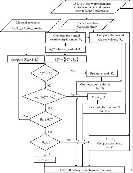
This approach for the implementation requires modelling the resin rich layer as a non-zero thickness medium. In fact, this layer has a finite thickness and the volume associated with the cohesive element can in fact set to be very small by using a very small thickness (e. g. 0.01 mm). To verify these procedures, the crack growth along the interface of a double cantilever beam (DCB) is studied. The two arms are modelled using standard LS-DYNA 8-node solid brick elements and the interface elements are developed in a FORTRAN subroutine using the algorithm shown in figure 4.
|
Fig. 4. Flow chart for traction computation in Mode-I |
The LS-DYNA code calculates the strain increments for a time step and passes them to the UMAT subroutine at the beginning of each time step. The material constants, such as the stiffness and strength, are read from the LS-DYNA input file by the subroutine. The current and maximum relative displacements are saved as history variables which can be read in by the subroutine. Using the history variables, material constants, and strain increments, the subroutine is able to calculate the stresses at the end of the time step by using the constitutive equations. The subroutine then updates and saves the history variables for use in the next time step and outputs the calculated stresses. Note that the *D AT ABASE _ EXTENT _ BINARY command is required to specify the storage of history variables in the output file.
|
Variable |
MID |
RO |
MT |
LMC |
NHV |
IORTHO |
IBULK |
IG |
|
Type |
I |
F |
I |
I |
I |
I |
I |
I |
|
Variable |
IVECT |
IF AIL |
ITHERM |
IHYPER |
IEOS |
|||
|
Type |
I |
I |
I |
I |
I |
|||
|
Variable |
AOPT |
MAXC |
XP |
YP |
ZP |
A1 |
A2 |
A3 |
|
Type |
F |
F |
F |
F |
F |
F |
F |
F |
|
Variable |
V1 |
V2 |
V3 |
D1 |
D2 |
D3 |
BETA |
|
|
Type |
F |
F |
F |
F |
F |
F |
F |
|
|
Variable |
P1 |
P2 |
P3 |
P4 |
P5 |
P6 |
P7 |
P8 |
|
Type |
F |
F |
F |
F |
F |
F |
F |
F |
|
where MID: Material identification; RO: Mass density; MT: User material type (41-50 inclusive); LMC: Length of material constant array which is equal to the number of material constant to be input; NHV: Number of history variables to be stored; IORTHO: Set to 1 if the material is orthotropic; IBULK: Address of bulk modulus in material constants array; IG: Address of shear modulus in material constants array; IVECT: Vectorization flag (on=1), a vectorized user subroutine must be supplied; IFAIL: Failure flag (on=1, allows failure of shell elements due to a material failure criterion; ITHERM: Temperature flag (on=1), compute element temperature; AOPT: Material axes option; MAXC: Material axes change flag for brick elements; XP, YP, ZP: Coordinates of point p for AOPT=1; A1,A2,A3: Components of vector a AOPT=2; V1,V2,V3: Components of vector v AOPT=3; D1,D2,D3: Components of vector d AOPT=2; BETA: Material angle in degrees for AOPT=3; P1..P8..: Material parameter (LSDYNA User’s Manual; LSTC, 2005). |
Table 1. Keyword cards for UMAT (LSDYNA User’s Manual; LSTC, 2005)
It is worth noting that the stable explicit time step is inversely proportional to the maximum natural frequency in the analysis. The small thickness elements drive up the highest natural frequency, therefore, it drives down the stable time step. Hence, mass scaling is used to obtain faster solutions by achieving a larger explicit time step when applying the cohesive element to quasi-static situations. Note that the volume associated with the cohesive element would be small by using a small thickness and the element’s kinetic energy arising from this be still several orders of magnitude below its internal energy, which is an important consideration for quasi-static analyses to minimize the inertial effects.


