As demonstrated previously, there are not many legal requirements to the design of the engine control room (ECR) and little guidance for this control centre. Thus the discussion in this section will be of a more informal character and based on
|
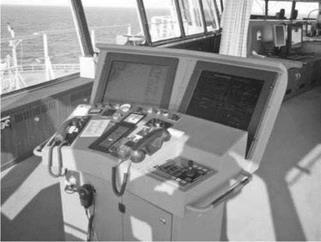
FIGURE 9.10 View towards the bridge wing with new console. (Design by Wallenius Marine AB/Furuno Finland. Photograph used with permission.) |
|
FIGURE 9.11 New bridge wing console, adapted to work when berthing. (Design by Wal- lenius Marine AB/Furuno Finland. Photograph used with permission.) |
empirical data (Andersson and Lutzhoft, 2007). As an example of the possibilities to use bridge guidelines for the ECR, we here present Table 9.4, which shows that if SOLAS V/15 were to be adapted to the engine department, its contents need little adjustment (compare Table 9.4 to Table 9.1).
We continue with a discussion of problem areas in the design of the ECR, supported by illustrations. The central piece of equipment here is, of course, the alarm system. The information provided by the alarm system must be easily accessible
TABLE 9.4
Suggested Adaptation of SOLAS V/15 to the Engine Control Room
Aim adaptation
Number
1.1 Facilitating the tasks to be performed by the ECR team in making full appraisal to the
situation and in running the ship safely under all operational conditions
1.2 Promoting effective and safe ECR resource management
1.3 Enabling the ECR team to have convenient and continuous access to essential information
that is presented in a clear and unambiguous manner
1.4 Indicating the operational status of automated functions and integrated components,
systems, and/or subsystems and alarms
1.5 Allowing for expeditious, continuous, and effective information processing and decision
making by the ECR team
1.6 Preventing or minimising excessive or unnecessary work and any conditions or
distractions in the ECR that might cause fatigue or interfere with the vigilance of the ECR team
1.7 Minimise the risk of human error and detecting such error if it occurs, through monitoring
and alarm systems, in time for the ECR team to take appropriate action
from every position in the control room. This is also valid for the acknowledgement of alarms. The development of technology has led to an increase in the number of alarms on board. Alarms will be further discussed in a later section.
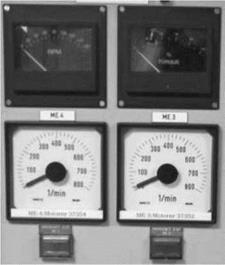
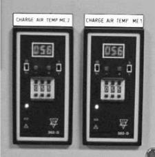
In order for an operator to maintain and update his or her mental model of the monitored processes both on the bridge and in the ECR, analogue presentations are often more helpful than digital. Reading errors are more common on digital instruments than analogue instruments. Analogue gauge indicators are in most cases preferred by engineers to digital gauge indicators (see Figure 9.12 and Figure 9.13). A specific value is more difficult to remember than the position of an indicator on an instrument. If the analogue instruments are designed in a way that implies that the needles of the instruments have the same position under ‘normal operation’, any deviations from the normal are easily detected (see Figure 9.14) (Wagner, 1994).
The instruments also need to be arranged due to their affiliation, the so-called functional grouping (see Figure 9.15). The layout must clearly show which knobs, switches, and indicator lights belong to a certain piece of equipment. For instance, controls for a pair of pumps, starboard and port, must be consistently mapped on the control panel in the same way (starboard and port). However, due consideration must be given to whether the control room or display surface is facing forward or aft. An issue discussed in many control rooms, as well as the ECR, is the loss of mimic boards, which often are replaced with computerised overviews. Care should be taken to provide operators with good overviews of systems, as well as giving them possibilities to zoom in on details.
|
FIGURE 9.12 Analogue instruments. (Personal photograph of M. Lundh.) |
|
FIGURE 9.13 Digital instruments. (Personal photograph of M. Lundh.) |


