The design of the engine control room should be guided by the functions that are to be performed there. A number of basic functions describe the work in a ship’s ECR and can be described as a group of tasks, duties, and responsibilities necessary for the operation of the propulsion of the ship and carried out in the ECR. The most basic functions that should be taken into account when designing this workplace are: [20]
|
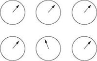
FIGURE 9.14 Deviation from the ‘normal’. (Image from E. Wagner. With permission.) |
|
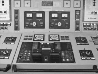
FIGURE 9.15 Functional grouping of instruments. (Photograph from E. Wagner. With permission.) |
• Emergency operation
• Planning and documentation
• Administrative duties
• Safety
• Communication
• Stand-by area
These functions are based on the functions described by IMO (2000) for the bridge, and are to be seen as a suggestion, open to discussion and revision. The specific design or placement of instruments is not discussed here, as these are dependent on the ship’s type and size. As far as ergonomics is concerned, relevant guidance for design is available in order to place the equipment within reach and sight. The workstation must also be adapted for both standing and seated work positions, as applicable. This is so that the working position can be varied during long work shifts.
Figure 9.16 shows a suggestion of an ECR layout, taking into account the above functions. The division of functions on these figures does not imply that they must or should be separated from each other physically. Figure 9.17 shows a good example of a well-designed ECR, where engineers are placed centrally with a good view over system and alarm status.


