in the second modeling example, a small tree is to be created. The basis for this example is a tutorial by Andreas Kathky which can be found also on the Greenworks website. The tree consists of four tree components that are linked together, and therefore has three branching levels. Here the structured creation of the geometry is especially important, since the parameter settings on the different branching levels might interfere, and thus the situation can easily become too complex when parameters on different levels have to be changed simultaneously.
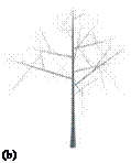
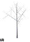
In the first step, a simple component is attached to the camera. It serves to scale and move the geometry that has to be rendered later on. In the default setting it will not generate its own geometry. The name of the component can be changed in the parameter editor, for example, name it “Scale”. In the next step, a tree component has to be attached to this component, this you name “Trunk”. The geometry created so far is at first only a stem (Fig. A.15b). If the second tree
 |
 |
|
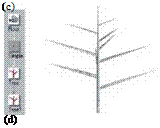
component is attached to the first one, a default branching structure such as that in Fig. A.15d, is created. However, this only occurs if the connection between the two tree components is a “multiple” link. As already mentioned, this can be set in the line under the structure editor, when the link is clicked. Name the second tree component “Branch1”.
Now two additional tree components are attached to the already-existing ones, and are named “Branch2” and “Branch3”. Again the link should be a “multiple”- link. In the following, the parameters for the components are set so that a young tree is created. We start at the “Trunk” component, and increase the number of segments to 70. This serves to more easily bend the trunk later on without the polygons becoming visible.
The modification of the geometry can best be controlled when a “wireframe” display is selected in the geometry window (Fig. A.16b). Up to now, the trunk had only three points per segment, and thus a triangular surface. This can be corrected by adjusting the number of points in the “Primitive” section; for example, select a value of 12.
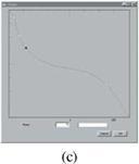
In the next step, the shape of the trunk is to be adjusted. In the parameter editor of the “Trunk” component, the field “Shape” is selected and set according to Fig. A.16c. Additional points can be produced by double clicking on the places where they should be inserted at the curves. Also, the branches of the first branching order have to be thinned out a bit. This happens in the same way as done with the “Branch1” component. Instead of calling up the editor, you can also change the approximated direct rendering in the menu by moving the points. Adjust each branch to be half the thickness of what it is at this moment. The changes will also affect all higher branching levels.
![]()
|
|
|

Appendix A We return to the “Trunk” component, and next we want to modify the angles
Practical Plant Modeling and the branching characteristics. Both can be adjusted in the parameter ed
 |
 |
 |
 |
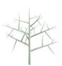
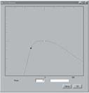
itor under the column “Branches”. The branching attribute “Distribution” is changed in the respective editor in such a way as to create fewer branches in the lower part than in the upper part (see Fig. A.17).
![]() (a)
(a)
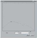
 in the same way, the branching attributes are entered under “Angle”. Here the function is set as shown in Fig. A.17c; the jags in the function are important to achieve a lively appearance of the model, and at the same time avoid branches that are too uniformly shaped.
 |
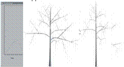 |
Actually, the branches should hang a little bit, meaning that a steeper branching angle has to be adjusted along the branch by bending. This occurs through the application of gravitropism, which affects the tendency of a structure to grow toward the ground. it can also be adjusted along the branch. For this you open the appropriate editor in the “Branch1” component, and set the curve similar to that in Fig. A.18a. Through bending, here the individual polygons of the geometry are becoming visible. This is avoided by simply increasing the number of segments in the “Branch1” component to about 70 (part c), if not already done.
Overall, the tree is still too compact. it is stretched by increasing the length of the “Trunk” component (all the way up in the “Tree” section). This should be set to about 35 (Fig. A.18d). If the tree has become too large for the screen, the its scale can be decreased to the desired size. This is done in the simple component named “Scale” just below the camera component within the “Basic” section. Alternatively, of course, the view can be modified by pressing the left and right mouse buttons while simultaneously dragging.
 Now we can continue with the refinement of the branches in the first order. Aside from the geometric scaling, there is a parameter named “Growth Scale” in Xfrog for the tree components. We mean here a structural scaling that not only enlarges a geometry but also increases the number of branches.
![]()
|
|
|
|

(a)

 |
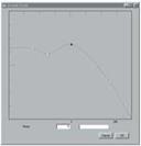
This kind of scaling is increased by using the editor in the “Trunk” component, since this value should be assigned to all branches of the first order. Figure A.19b shows the amplified branches. Simultaneously, also the lengths of these branches should be decreased to create a more slender tree. For doing so, reduce the length parameter of the “Branch1” component to 16 (Fig. A.19c). Now it is time to turn to the branching levels. Firstly the branches have to be shortened. Here we use the “Branch2” component and again the “Shape” parameter (see Fig. A.20a). Additionally, the angles of the branches are increased. This takes place by changing the respective parameters in the “Branch2” component: increase the angle in the upper area of the branches (Part c) to lower the curve.
(b)
Currently there are too few branches in the second branching order. If we simply were to increase the number in “Branch1”, then they would only appear in the upper part of the crown. This is caused by the “Distribution” parameter in “Branch1”, which does not permit branching at the beginning of the structure. While this is a good setting for tree trunks, the branches should however be distributed along the entire length. Therefore, activate the “Distribution” parameter of the “Branch1” component, and we see that there are actually almost too many branches; thus correct this by adjusting them with the “Number” parameter.
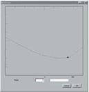
 Figure A.21
(a) Editor for “Density” in the “Branch2” component;
(b) adjusting the parameter
(a)
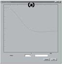
There is a second parameter that influences the number of the branches; the “Density” parameter. This parameter indicates the density produced by the multipliers and thereby has a wide-ranging effect. Select this parameter in the “Trunk” component according to Fig. A.21a. Now we still have to adjust some other parameters: “Number” in “Trunk” to 13, and also in “Branch1” as well as “Branch2” to eight.
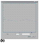


The “Screw” parameter controls the deviation angle, with which the branching deviates from a tree component. it can be used to realize typical tree branching or to render the model livelier. Set this parameter in the “Trunk” component as shown in Fig. A.22a, and set the same parameter for the “Branch1” component according to Fig. A.22b.
Let us now look at the last branching level. Here it is necessary to first apply a higher density, so that this level becomes more noticeable. Additionally, change the branching attributes in the “Branch2” component, so that more branches are created at the beginning (Fig. A.23a). Then lower the branches a bit in the “Branch2”. The result should be similar to that in Fig. A.23b.
Now the branches of the second branching order (“Branch2”) appear distorted because of their straightness. Correct this, i. e., bend them downward using gravitropism.
Actually the tree looks very nice so far, but it appears to be too straight. Natural trees often change their direction of growth, such as when branching out at a certain place. This process can take place using the deviation parameter: increase it uniformly along the entire length of the trunk and branch in the “Trunk” and “Branch1” components, respectively. The end result is shown in Fig. A.23c.
 |
 |
 |
 |
Now attach the leaf component to the “Branch3” component. It is important that it is joined with a “multiple” link to the “Branch3” component. In the leaf, change the primitive to “Triangle up”. Now, only a single triangle is produced; this is useful if many leaves have to be created. Apply the texture named “leaf. png” to this triangle and adjust the scaling so that the complete leaf becomes visible. Now apply the “bark. png” texture to the surface of the “Trunk” component.


 |
In Fig. A.24a we show the leaf geometry, and in part b the complete model. If you have problems setting the texture parameters for the leaf, just attach it directly to the camera, and hide the rest of the geometry by selecting the “Scale” component and by activating “Hide” below the structure editor.
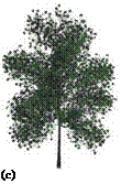
To enrich the model, select the “Trunk” component and carefully increase the “Growth scale” parameter until more leaves appear, especially in the upper part of the plant. Now increase the number of the branching in the “Branch2” and “Branch3” components to about a value of 12. Our version of the final result is shown in Fig. A.24c.


