A major problem in the monitoring of extremely strained composite structures is the early detection and identification of defects arising in the structure of the material. The defects can be the result of material fatigue under cyclic loads (e. g. filling and emptying of the vessel) or other events, e. g. external impacts or the exceedance of the allowable stress (pressure) and working temperature.
The standards relating to the testing of pressure vessels for storing high-pressure fuels (ECE Regulation No. 110, 2008; ISO/DIS15869.3, 2008) distinguish two main types of defects: flaws and delaminations. According to the cited regulations, a vessel with a flaw should meet the requirements of, among others, the cyclic tests at room temperature for a vessel without visible flaws.
Tests of vessels with flaws are referred to in the standards as composite flaw tolerance tests. Depending on the standard, the size of a flaw can be defined as "larger than the limit for the visual inspection, specified by the vessel manufacturer" and so no smaller than:
– length 25mm x depth 1.25mm,
– length 200mm x 0.75mm depth.
 |
The flaws are made (by cutting) in the vessel’s composite shell in the direction parallel to its principal axis (Fig. 13). As already mentioned, after the flaws are made the vessel is subjected to the standard cyclic test whose result is deemed positive if the vessel does not fail (loss of airtightness or burst).
 |
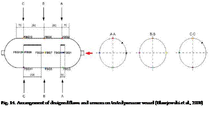
A pressure vessel for storing hydrogen at NWP = 207 bar (3000 psi) with 12 fibre Bragg gratings installed and two designed flaws in the form of cuts (Fig. 14) was subjected to a cyclic test at room temperature. The test consisted of over 4050 cycles in a pressure range of 20-258.5 bar (1,25 x NWP).
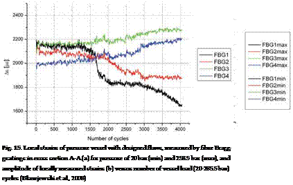
The measured local strains in a cross section with the shorter flaws (cross section A-A) are shown in Fig. 15. Figure 15a shows the minimum (emin) and maximum (emax) strains registered by sensors FBG1-FBG4 for pressures 20 and 285.bar. Fig. 15b shows the variation in strain amplitude (emax – emin) versus vessel load cycles. It should be noted that in the

analyzed cross section as the number of load cycles decreases so does the strain values registered by sensors FBG1 and FBG2 located closest to the flaw. At the same time the amplitude of the strains registered by the other sensors increases. This is evidence of local defects accumulation in the load-bearing shell of the composite vessel and of the growth of the designed flaw.
The fluctuations of the maximum and minimum strain values are due to the specific character of the cyclic tests, i. e. due to the actual fluctuations of the maximum and minimum internal pressure around the fixed value (the switching pressure).
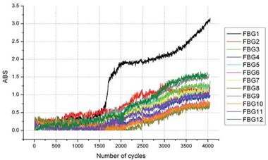
Figure 16 shows an analysis of the ABS coefficients for each of the FBG sensors installed on the tested pressure vessel, carried out in accordance with the description in sect. 5.2. It should be noted that as the number of pressure cycles increases so does the value of each of
the analyzed ABS coefficients. This indicates the growth (accumulation) of defects in the tested vessel.
|
Fig. 16. Analysis of ABS coefficients versus number of pressure cycles for all FBG sensors installed on tested vessel with designed flaws (Blazejewski et al., 2008) |
The largest changes were registered by sensors FBG1, FBG2, FBG11 and FBG 12, i. e. the sensors located closest to the introduced designed flaws. Moreover, one can see that the variation of the ABS coefficient, registered by sensor FBG1 after about 1600 cycles sharply increased during the next cycles. This indicates intensive local accumulation of defects, whose increase slowed down in the interval from ~2000 to ~3000 cycles, and then began to sharply increase again.
2. Conclusions
– The increasing use of polymer composites in various engineering structures necessitates the application of novel effective techniques of measuring mechanical quantities. Preferred are nondestructive techniques which would be inexpensive, reliable over the long service life of engineering structures and resistant to external influences. Measuring techniques are also expected to satisfy the requirements which structural health monitoring (SHM) systems have to meet. Systems based on optical fibre sensors (OFS) satisfy most of the requirements.
– The OFS technology offers the possibility of implementing "nervous systems" for infrastructure elements that allow health and damage assessment. Provided proper procedures are followed, optical fibre sensors can be located between the reinforcement fibres inside the composite material without affecting the mechanical properties of the composite element. Optical fibre based sensors can be used for measurements in adverse conditions (e. g. strong electromagnetic interference, high temperature and humidity) in which conventional methods cannot be used. Measuring heads based on fibre Bragg gratings have proved to be particularly suitable for composite structures. Also interferometric sensors (e. g. EFPI, SOFO®) can be used to some extent for this purpose.
– The increased interest in the novel measuring methods is also due to the many advantages of OFS over the conventional measuring methods. In practical applications measuring heads based on fibre Bragg gratings have been used most often.
– A major advantage of optical fibre sensors is that they can be used to build SHM systems comprising several thousand measuring points. This is particularly valuable when the object to be monitored is large or when it is not possible to determine the weak (critical) points in its structure. Thanks to the installation of many sensors the calculation methods can be simplified and the possibility that important information concerning the operational safety will be overlooked can be reduced. In addition, such systems are lightweight (in comparison with, e. g., strain gauge systems) and require little cabling.
– OFS can be used for on-line structural health monitoring. A major field of their application are extremely strained pressure vessels for fuel gas (methane, hydrogen). It was demonstrated that the OFS system is capable of detecting and controlling the growth of defects arising in the structure of composite materials whereby the safe service life of pressure vessels can be determined. Thanks to the way in which optical fibre sensors are installed it is possible to diagnose the health of structures during both their manufacture and long service life.
– Exemplary applications to building elements (reinforced concrete beams), composite aerospace structures and new generation of composites stimulated with a magnetic field (SGMM composites) were described.


