Three carbon fiber laminate samples are constructed for this study. Each sample is fabricated from TORAY T700CF carbon fiber bidirectional weave and DERAKANE 510-A vinyl-ester matrix resin. Each plate is fabricated through the Vacuum Assisted Resin Transfer Molding (VARTM) process, which consists of pulling resin through layers of carbon fibers using a vacuum pump. The plates consisted of eight plies oriented [0/90/0/90]s at 2.38 mm nominal thickness with dimensions of 457 x 457 mm. The DERAKANE resin is mixed with three hardeners, Methyl Ethyl Ketone Peroxide (MEKP), Cobalt Napthenate (CoNAP), and N – Dimethylaniline (DMA) to achieve a nominal 60 minute curing time. The hardeners are added solely to achieve proper gel time and do not affect composite strength. All resin components are mixed based on a percent weight for a nominal cure time per manufacturer’s directions at
a temperature of less than 70°F. The DERAKANE 510-A is measured by volume and the MEKP, CoNAP, and DMA are measured by weight.
 |
 |
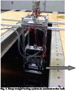
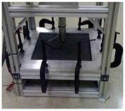
Impact tests are conducted using a specially designed drop weight testing system, as shown in Fig. 1. This instrumented apparatus consists of a drop weight impactor, a load transducer, strain gages, high speed data analyzer, and an air box. The sample supporting fixture at the bottom of the drop tower is made of aluminum and facilitated square clamped conditions with a clear span of 305 x 305 mm. The composite plates are then clamped to the impactor frame using c-clamps to represent clamped boundary conditions. The transient response measurement of the sample includes force and strains as a function of time.
The drop weight impactor consists of a drop weight and an impact rod. The drop weight is supported by 4 steel guide rods, and the impact rod is supported by an aluminum frame base and a linear spring of spring constant 7508 N/m. The dimensions of the guide rods are 1.219 m high with a 6.35 mm diameter, and the dimensions of the base frame are 1.168 m high x 0.457 m wide x 0.457 m deep. The aluminum framing pieces and fasteners are designed and assembled for this research. The falling weight is guided by four small linear bearings. The impact rod is guided with two plain brushing aluminum linear bearings of 38.1 mm diameter enclosed in a casing for support. The top of the impact rod stays above the water surface so that the drop weight does not go into the water as it hits the impact rod on its top. It is important not to disturb the water during the impact testing so that a composite plate interacts with still water. The other end of the impact rod, which strikes a composite plate during impact, is located initially very close to the specimen surface inside the water such that the disturbance of water due to the impact rod is negligible. Therefore, FSI occurs only resulting from dynamic motion of composite plates.
A trigger at the base of the falling weight is used to measure data collection. The drop weight is kept constant at 12.0 kg. The impact rod is made of steel and has a mass of 12.7 kg. Impact energy can be varied by changing the drop height. The maximum height is 1.06 m, which can produce approximately 4.6 m/s initial velocity upon impact. The impact location is at the center of the composite sample. The selection of impact mass and height is made not to cause any damage to the composite plates so that transient dynamic response of the plates can be focused in the study.
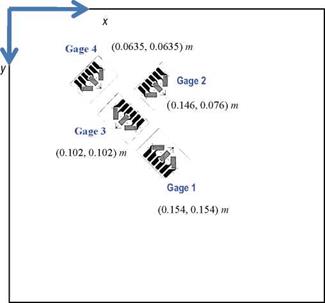
The load cell used is an ICP® force sensor manufactured by PCB Piezotronics, Inc. which converts force into a measurable electrical output. The load transducer is mounted on the end of the impactor rod. The gage has an impact diameter of 15.88 mm. In the case of wet testing, the gages and cable connection are coated. The strain gages are three-element 45° single-plane rosettes, model CEA-00-250UR-350, by Vishay Micro-Measurements. There are four rosette strain gages bonded to each composite sample. The gages are bonded to the underside of the laminate samples, opposite side of impact, and waterproofed. Fig. 2 illustrates the orientation, location and designated x-y axis. Gage location #1 is directly at the center on the underside of the sample opposite the impact location. Gages #3 and #4 are placed along a diagonal line of the composite plate with Gage #4 at the quarter distance of the diagonal length. Gage #2 is located close to the vertical symmetric line of the center.
|
Fig. 2. Strain gage rosette locations opposite the side of impact. |
Data acquisition is carried out using an acquisition system specifically developed for this project, that consists of a Pentium™ 4, 2.4 GHz, 512-MB RAM system, National Instruments™ simultaneous sampling multifunction DAQ, and five Vishay™ 2120 multichannel strain signal conditioners. The system has a 16 bit analog-to-digital conversion resolution and is capable of reading a total of 16 channels at a throughput rate of up to 250 kS/s per channel, which is appropriate for the rate of testing used in this study. The data-
acquisition process is controlled using the NI-DAQmx driver software and Lab VIEW™ interactive data-logging software that is specifically formatted for this research. A trigger located at the top of the impact rod is used to initiate data acquisition. Strain readings from four signal conditioners are multiplexed in order to accommodate all strain gages within the available number of channels. Errors due to instrumentation noise do not appear to cause problems in the data capture so no filtering is used.
An air box is specifically constructed to facilitate testing for air-backed wet environments. The box is made of 12.7 mm thick plexi-glass with dimensions 330 mm wide x 330 mm long x 127 mm deep. This box is then secured to the bottom aluminum support plate for the composite sample using 8 c-clamps of dimensions 76 mm jaw x 60 mm throat, and sealed with putty tape to prevent water leakage. The box completely covers the sample so that the bottom side of the plate is not exposed to water. A 19 mm diameter hole is cut out from the side to feed the wiring from the strain gages to the data analyzer, which is filled with putty to prevent water leakage during testing.
An anechoic water tank used for underwater surroundings testing is measured 2.75 m wide x 2.75 m long x 2.75 m deep. The anechoic tank is used to minimize the influence of the wave reflection from the boundary walls. The tank is filled with fresh water. A standing platform is constructed across the top of the tank made with aluminum I-beams and plywood, leaving a 0.635 m x 0.914 m square opening for suspension of the drop weight impactor.


