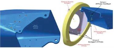
The features of the Hoist Mount are the two planes and the two patterns of six holes that allow to couple the part with the After and Forward Frame. The holes have a dimensional tolerance of ±0.25 mm. The Y-axis of the Datum Reference Frame passes from the centre of the holes 1 and 2 of the pattern that allows to couple the After Frame, as shown in Fig. 13 on the left. The Z-axis is perpendicular to the coupling plane with the After Frame and the X – axis is perpendicular to ZY plane. The origin is in the centre of the hole 2 of the pattern projected on the coupling plane.
|
|
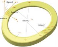
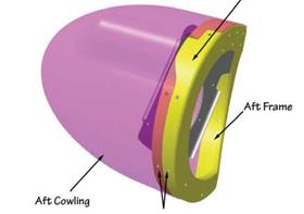
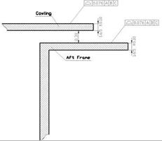
The features of the After Frame are the pattern 1 of six holes that couples the part with the Hoist Mount and the pattern 2 of four holes that couples the part with the Box Support, as shown in Fig. 14. The X-axis of the Datum Reference Frames is due to the intersection of the two planes containing the two patterns. The Z-axis is perpendicular to the plane that contains the pattern 1 and that mates the Hoist Mount. The Y-axis is perpendicular to ZY plane. The origin is due to the intersection of the X-axis with the cylindrical surface on the side of the After Frame. Moreover, there are two further patterns of six and eight holes on the lateral cylindrical surface for the coupling with the Mid Cowling and the After Cowling (see Fig. 15). All the holes have a dimensional tolerance of ±0.25 mm. To the lateral cylindrical surface a profile tolerance of 0.076 mm and a dimensional tolerance to the thickness of ±0.10 mm are applied, as shown in Fig. 16.
The same features and the same datum reference frame may be found in the Forward Frame.
|
Fig. 14. Features and Datum Reference Frame of the After Frame |
|
Fig. 15. Coupling of the After Frame with the After Cowling |
The features of the Box Support are constituted by a pattern of four holes that allows to couple the After Frame, the central hole where the axis of the engine of the winch arm is fitted and the pattern of six holes that allows to fix the engine (see Fig. 11). The central hole and the pattern of six holes lie on the same plane. The pattern of four holes lies on a plane that mates with the plane of the After Frame. The Z-axis of the Datum Reference Frame is perpendicular to the plane where the central hole lies. The origin is the centre of the hole to fit the engine. The X-axis connects the origin with the centre of one hole of the pattern to fix the engine. The holes of the patterns have a dimensional tolerance of ±0.25 mm.
The After Cowling is constituted by a cylindrical surface, that is signed in blue in Fig. 12, where there is a pattern of eight holes for coupling it to the After Frame. To this surface a profile tolerance of 0.076 mm is applied, while its thickness has a dimensional tolerance of ±0.10 mm (see Fig. 16). Moreover, it has an elliptical surface, that is signed in pink in Fig. 12, with aerodynamic properties. The Datum Reference Frame is located in the centre of the ellipse that generates the cylindrical surface for coupling with the After Frame. The Y-axis is parallel to the largest axis and the X-axis is parallel to the smallest axis of the ellipse. The Z – axis is perpendicular to YX plane with a positive orientation outside the material. The origin is in the centre of the ellipse.
The same features and the same datum reference frame may be found in the Forward Cowling.
|
Fig. 16. Tolerances applied to the coupling surfaces of the After Frame and the After Cowling |
The applied tolerances have been considered distributed as a Gaussian probability density function, whose parameters (mean and standard deviation) have been estimated as the nominal value of the surface property and one third of the applied tolerance range respectively.


