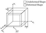
The imposition of canonical states of strain upon the representative volume element utilizing finite-element analyses requires the development of a corresponding set of displacement boundary conditions. The representative volume element principal directions, (e1, e2, e3) are shown in Figure 1. Equation 10 defines the appropriate displacement boundary conditions for the prescribed extensional strain in the "1" direction with ui representing the displacement vector and xi the position vector.
|
U (0,X2,X3 ) = Txy (0,X2,X3 ) = Txz (0,X2,X3 ) = 0 |
(10a) |
|
U (L1, X2, X3 ) = S1L1; Txy (L1, X2, X3) = Txz (L1, X2, X3) = 0 |
(10b) |
|
v (X1,0,X3) = Tyx (X1,0,X3) = Tyz (X1,0,X3) = 0 |
(10c) |
|
v (X1, L2, X3 ) = Tyx ( X1, L2, X3 ) = Tyz ( X1, L2, X3) = 0 |
(10d) |
|
w(x1,x2,0) = Tzx (x1,x2,0) = Tzy (x1,x2,0) = 0 |
(10e) |
|
w (X1, X2, L3) = Tzx (X1, X2, L3) = Tzy (X1, X2, L3) = 0 |
(10f) |
|
As an example, Equation 11 gives the canonical shearing displacements for shearing in the |
2-3 plane.
u (0,X2, X3 ) = Txy (0, X2,X3 ) = Txz (0,X2,X3 ) = 0 (11a)
u (L1, X2, X3 ) = Txy (L1, X2, X3 ) = Txz (L1, X2, X3 ) = 0 (11b)
w(X1,0,X3) = &w (X1,0,X3) = TyX (X1,0,X3) = 0 (11c)
w(x1,L2,X3) = Y23L2I2; Pyy (X1,L2,X3) = TyX (X1,L2,X3)= 0 (11d)
v (X1,X2,0)=&zz (X1,X2,0) = Tzx (X1,X2,0) = 0 (11e)
v (X1, X2, L3 ) = Y23L3/2; dzz (X1, X2, L3 ) = Tzx (X1, X2, L3 )= 0 (11f)
This simple set of displacement boundary conditions are only valid for doubly periodic representative volume elements. In general, further constraints are required on the displacement field to maintain periodicity between adjacent unit cells. However, periodicity is satisfied automatically in the symmetric unit cells studied here. The desired average strain is recovered by inserting the boundary conditions shown in Equations 10 and 11 into Equation 6. The nodal forces taken from each face of the representative volume element can then be used in Equation 6 to determine the average stress and thereby provide the homogenized material properties as discussed in Section 2.
For the case of a uniform temperature change of the representative volume element, boundary conditions are imposed to allow for free expansion of the representative volume element with the constraint that all faces must remain planar. This condition results from Equation 8 that requires the representative volume element to exhibit the free thermal deformation aAT in order that the homogenized mechanical strains vanish. In this case, free thermal deformation of representative volume element is equal to that defined by the coefficients of thermal expansion of the homogenized unidirectional lamina, aAT. The planar constraint is required to maintain periodicity between adjacent volume elements. Procedures to implement these constraints are implemented in both Abaqus (© Dassault Sytemes) and StressCheck® (ESRD). For StressCheck® when the analysis is performed for any given load, the program will create constraint equations for all the degrees of freedom associated with the selected faces. The internal degrees of freedom (faces and edges) are eliminated at the element level (local constraint equations), while the equation for the nodal variables are written in compact form at the global level.
|
Fig. 2. Constrained deformation due to thermal loading. All faces remain planar to maintain periodicity |
Since each face is constrained to remain planar, no average shearing strain will be obtained. The normal strain components are given in Equation 12. Using the normal strain components, the homogenized coefficients of thermal expansion can be determined with Equation 4, where U, V and W are the displacement components shown in Figure 2. It should be noted that these displacements are unknown prior to performing the analysis.
S1 = , S2 = , £э = (12)
L1 L2 L3


