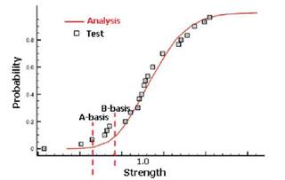
The computational capability described herein is validated for polymer composite materials typically used in aerospace applications. Data for MTM45-1 145 AS4, IM7/MTM45 graphite/epoxy and T300/PPS material are used to demonstrate the effectiveness of the methodology. Additionally, the capability of obtaining A-basis starting from B-basis is demonstrated.
Strength Allowables for MTM45-1 145 AS4 (Lamina Level)
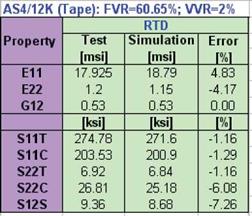
mechanical properties while Table 4 lists similar properties for the MTM45 matrix. The derived constituent properties combined with ply manufacturing parameters of 61% fiber volume fraction and 2% void volume fraction reproduced accurately the average ply properties reported from test in [7]. A comparison of calculated ply properties by MS-PFA simulation and test is presented in Table 5. With accurate determination of average ply properties starting from in-situ fiber matrix properties, random variables statistics for microscale mechanical properties are obtained directly from lamina level testing published in [7]. Table 6 lists the derived random variables statistics for use in determination of strength allowables for MTM45-1 145 AS4. The COVs of strength and stiffness properties were obtained from lamina level tests published in reference [7] while the COVs of other random variables were iterated on to ensure proper simulation of lamina level scatter. The considered random variables included fiber and matrix stiffness and strength and fiber and
ЄЛ2) Fiber (l) і □ AS4
Description:
Calibrated from Input Ply Properties: j FVR=0,6065; VVR=0.02 I Li & Mechanical I Modulus
І І…… Ell = 3.139E+07 ІЬҐ/(іпл2)
і ; E22 = S. tllElCt 1Ы, і (. і 2)
‘ b-G12 = 5.318E+06 ІЬР/(іпл2)
I L G23 = 1.234E4-06 lbf/(in^2)
I Poisson Ratio
I I. MU 12 = 2.895E-01
І L NU23 = 4.632E-Q1
I a® Strength
SI IT = 4.500E+05 ІЬР/(іпл2)
SI 1C = 3,120E+05 ІЬР/(іпл2)
Table 3. AS4 Fiber In-Situ Properties
MatriH (1)
І Й -0 MT45
Description:
Calibrated from Input Ply Properties: і FVR=0.6065; VVR=0.02 ! Mechanical
! Q9 Modulus
І……. E = 3.495E+05 ІЬР/(Іпл2)
! ad Poisson Ratio
; – MU – 3.400E-01
І Strength
I.. ST = 1.O75E+04 lbf/(in^2)
■■■■■SC = 4.00OE4-04 lbf/(in^2)
‘■■■■55 = 1.40OE4-04 ІЬ1/(іпл2)
Table 4. MTM45 Matrix In-Situ Properties
|
|
Table 5. Comparison of Average Ply Properties Obtained from Test to those from Simulation for MTM45-1 145 AS4
|
Fiber-Matrix Properties Random Variables |
Mean Value |
COV |
Standard Deviation |
Distribution Type |
|
Fiber Ef11 – Longitudinal modulus (msi) |
31.39 |
3.0% |
0.9417 |
Normal |
|
Fiber Sf11T- Longitudinal tension strength (ksi) |
450 |
5.5% |
24.75 |
Normal |
|
Fiber S11C – Longitudinal compression strength (ksi) |
312 |
5.0% |
15.6 |
Normal |
|
Matrix Em – Normal modulus (msi) |
0.3495 |
3.1% |
0.018345 |
Normal |
|
Matrix SmT – Matrix tension strength (ksi) |
10.75 |
17.5% |
1.881 |
Normal |
|
Matrix SmC – Matrix compression strength (ksi) |
40 |
5.0% |
2 |
Normal |
|
Matrix SmS – Matrix shear strength (ksi) |
14 |
4.0% |
0.56 |
Normal |
|
Manufacturing Parameters Random Variables |
Mean Value |
COV |
Standard Deviation |
Distribution Type |
|
Fiber content (%) |
60.65 |
4% |
2.426 |
Normal |
|
Void content (%) |
2 |
2.5% |
0.05 |
Normal |
|
Table 6. Random Variables Statistics for Use in Determining Allowables for MTM45-1 145 AS4 Composite |
void contents. The COVs for the mechanical properties were obtained from lamina level testing published in reference [7] using the correlation between measured ply property and micro-scale properties of Table 2. The COVs for the manufacturing variables were obtained by iterating on the scatter produced by combined MS-PFA and probabilistic analysis to match the one from lamina level testing of the five in-plane ASTM tests of Figure 3.
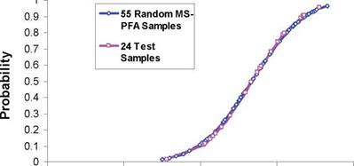
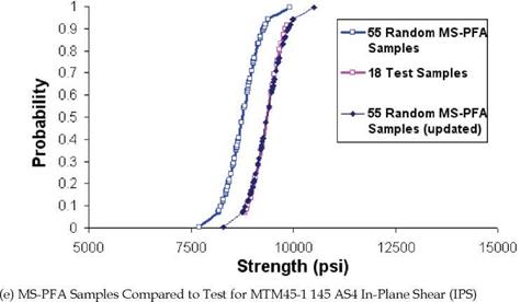
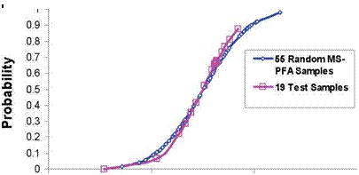
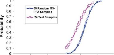
Figure 6 shows the lamina level cumulative distribution functions (CDFs) for the 5 in-plane ASTM tests LT, LC, TT, TC, and IPS generated from virtual test data using MS-PFA simulation and from actual test. The data from test and simulation are fitted to a normal distribution in the plots (a) through (e) for the various ASTM tests. The amount of data reported in reference [7] for each ASTM type varied. For example, for the LT test, 19 samples were reported while for LC a total of 24 samples were reported. The CDF from simulation was generated for each test using the random variables statistics listed in Table 6. A total of 55 samples were randomly generated with MS-PFA considering simultaneous uncertainties in material and manufacturing random variables. That means MS-PFA was run 55 times for each ASTM test to predict failure stress for each sample. All variables listed in Table 6 took on random values for each analysis sample by MS-PFA. As illustrated in Figures 6-a through 6-c, the distribution (scatter) and mean strength generated by the simulation matched perfectly the ones from test for LC, LT, and TT tests.
 |
The data generated for TC and IPS are shown in Figures 6-d and 6-e. The CDFs from simulation are updated for TC and IPS per the procedure outlined in Figure 5 for fine tuning the COV variables. Initial predictions for mean strength from simulation were 5.5% and 6.3% lower than average from test for TC and IPS. The updates, although not necessary, are done to ensure that the mean strength from simulation matches exactly the mean from test. This process allows the analyst to correlate data from test with simulation and update the simulation results with test data regardless how limited the data is. The difference between mean predicted and test strengths for TC and IPS specimens could be have been reduced to a negligible value by adjusting the calibrated in-situ properties. However, the authors intended to illustrate that the difference in mean strength between simulation and test depicts a realistic situation.
200000 250000 300000 350000
Strength (psi)
|
|
150000 170000 190000 210000 230000
Strength (psi)
(b) MS-PFA Samples Compared to Test for MTM45-1 145 AS4 Longitudinal Compression (LC)
|
|
|
|
20000 25000 30000 35000 40000
Strength (psi)
|
(d) MS-PFA Samples Compared to Test for MTM45-1 145 AS4 Transverse Compression (TC)
Fig. 6. Scatter in Failure stress for LT, LC, TT, TC, and IPS Generated by MS-PFA Simulation for MTM45-1 145 AS4 Compared to Lamina Level Test Data [7] |
Based on accurate reproduction of strength scatter with MS-PFA from test, one concludes that the uncertainties defined are valid for use in laminate level simulation of notched or unnotched specimens. If the scatter produced from simulation is not accurate, other physical random variables can be included in the analysis while iterating on the COV to match the scatter at the lamina level.
The virtual test samples data produced by MS-PFA are run with STAT-17 [2] to determine A – and B-basis values. Table 7 compares the A – and B-basis values from the 55 samples generated
by MS-PFA to those reported in reference [7]. The samples generated virtually by MS-PFA are analyzed using STAT-17 to determine A – and B-basis values. The results obtained from STAT – 17 for MS-PFA samples met the normality criterion. Note that the allowables reported in [7] for TT and IPS tests were obtained using ANOVA method (a very conservative criterion). The advantage of simulation lies in its capability of providing alternate approach to avoid unreasonable allowable strength values when CMH-17 criteria are not met.
|
Lamina |
Test Mean |
MS-PFA Mean |
Test Report [7] |
MS-PFA* |
% Diff |
|
Test |
Strength (ksi) |
Strength (ksi) |
A-Basis (ksi) |
A-Basis (ksi) |
w. r. [7] |
|
LT |
274.78 |
275.18 |
234.76 |
224.01 |
-4.58% |
|
LC |
203.53 |
203.38 |
168.23 |
172.55 |
2.57% |
|
TT |
6.92 |
7.05 |
0. 48** |
3.68 |
N/A |
|
TC |
26.81 |
25.36 |
21.61 |
21.71 |
0.46% |
|
IPS |
9.36 |
8.76 |
4.97** |
7.61 |
N/A |
|
Lamina |
Test Report [7] |
MS-PFA |
% Diff |
||
|
Test |
B-Basis (ksi) |
B-Basis (ksi) |
w. r. [7] |
||
|
LT |
250.71 |
245.80 |
-1 .96% |
||
|
LC |
182.47 |
185.68 |
1 .76% |
||
|
TT |
0** |
5.12 |
N/A |
||
|
TC |
24.26 |
23.27 |
-4.08% |
||
|
IPS |
6.8** |
8.10 |
N/A |
|
* Randomly generated with MS-PFA then used as input to STAT-17 (Normal) "Reference [7] used ANOVA method to report allowables Table 7. Validation of MTM45-1 145 AS4 Lamina Level Allowables Obtained Using Virtual Test Samples by MS-PFA (Simulated Samples are Inputed to STAT-17) |
|
Table 8 lists lamina level allowables obtained from simulated CDF at 0.01 probability for A – basis and at 0.10 probability for B-basis are compared to those reported in reference [7]. Overall, generating samples randomly with MS-PFA and processed with STAT-17 produce similar allowables to those obtained from a CDF for the given ASTM test. However, the CDF curve would depict more stable allowables as it is not dependent on tolerance factors. Next, results obtained for laminate level allowables are presented and discussed.
* Obtained from CDF of Probabilistic Strength (A-basis at 0.10 Probability; B-basis at 0.1 Probability) "Reference [7] reported use of ANOVA for this prediction |
Strength Allowables for MTM45-1 145 AS4 (Laminate Level without use of Test Data)
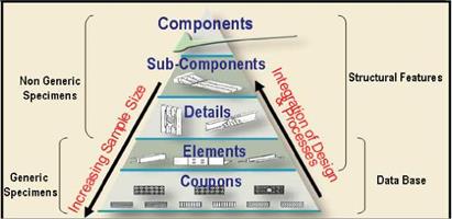
A major contribution of the work presented here is the ability to use lamina level uncertainties to predict uncertainties for any laminate. Micro-scale uncertainties are infused to higher level structures of the FAA building block of Figure 7. The uncertainties derived in Table 6 are used to determine A – and B-basis allowables for un-notched laminate specimens for two layups: [0/90]s and quasi-isotropic (25% 0° plies, 50% ±45° plies, and 25% 90° plies). The allowables were obtained with MS-PFA for tension and for compression loading conditions. Figure 8 shows plots of the CDF of strength determined using the same uncertainties used in the lamina level simulation. Table 9 lists the values for A – and B-basis obtained from MS-PFA simulation and from reference [7] using standard methods.
|
Fig. 7. FAA Building Block Validation with Generic and Non-Generic Specimens Depicting Multi-Scale and Multi-Level Integration of Structural Parts |
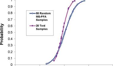
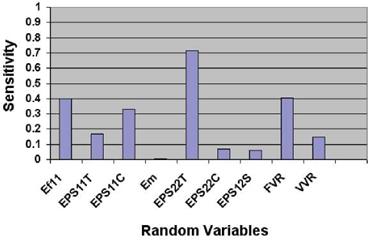
In Figure 8, strengths from physical testing are plotted alongside the strengths generated with MS-PFA. This is done to illustrate the degree of fitness of simulated data compared to test. The allowables values listed in Table 9 are obtained from simulation using the uncertainties of Table 6 and assuming data from physical testing are not available. Figure 9 shows the probabilistic sensitivities of random variables for the quasi-isotropic laminate. The sensitivity analysis ranks the random variables by order of influence on the laminate strength response. This is done by identifying the "root cause" for composite damage and failure. Controlling variability in the influential random variables reduces scatter in laminate strength response. As can be concluded from Figure 9, the transverse tensile strain EPS22T is the most predominant uncertainty followed by fiber volume ratio, FVR. Note that for laminate level specimens, a strain failure criteria is used for ply failure analysis in MS – PFA while for lamina level specimens, strength based criteria were used. The random variable statistics remain unchanged as the evaluation moved from lamina level to laminate level. Strain limits used as fracture criteria for laminate analysis are derived from lamina analysis and the reverse engineering process of fiber and matrix properties discussed earlier (Table 3 and Table 4).
|
70000 90000 110000 130000 150000 170000
Strength (psi)
 |
(a) MS-PFA Samples Compared to Test for 0/90 MTM45-1 145 AS4 Un-notched Tension
70000 80000 90000 100000 110000 120000 130000
Strength (psi)
|
|
70000 80000 90000 100000 110000 120000
Strength (psi)
(c) MS-PFA Samples Compared to Test for MTM45-1 145 AS4 Quasi Isotropic Un-notched Tension
|
|
40000 60000 80000 100000 120000
Strength (psi)
(d) MS-PFA Samples Compared to Test for MTM45-1 145 AS4 Quasi Isotropic Un-notched Compression
Fig. 8. Scatter in Laminate Level Failure Stress for MTM45-1 145 AS4 0/90 and Quasi Unnotched Specimens Generated by MS-PFA Simulation Compared to Test Data [7]
|
Test Type Un-Notched |
Test Mean |
MS-PFA Mean |
Test [7] |
MS-PFA* |
Difference |
|
Strength (ksi) |
Strength (ksi) |
A-Basis (ksi) |
A-Basis (ksi) |
w. r.t [7] |
|
|
0/90 Tensile |
143.74 |
142.96 |
122.82 |
125.87 |
2.48% |
|
0/90 Compressive |
108.07 |
112.47 |
89.71 |
91.30 |
1.77% |
|
Quasi Tensile |
108.82 |
110.62 |
95.35 |
99.80 |
4.67% |
|
Quasi Compressive |
78.81 |
80.62 |
68.51 |
61.15 |
-1 0.74% |
|
Test Type Un-Notched |
Test[7] |
MS-PFA |
Difference |
||
|
B-Basis (ksi) |
B-Basis (ksi) |
w. r.t [7] |
|||
|
0/90 Tensile |
131.16 |
129.20 |
-1 .49% |
||
|
0/90 Compressive |
97.09 |
104.02 |
7.14% |
||
|
Quasi Tensile |
100.83 |
104.41 |
3.55% |
||
|
Quasi Compressive |
72.63 |
69.44 |
-4.39% |
|
* Randomly generated then used as input to STAT-17 (Normal) Table 9. Validation of MTM45-1 145 AS4 Laminate Level Allowables Obtained Using Virtual Test Samples by MS-PFA (Simulated Samples are Input to STAT-17) |
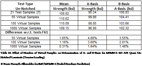
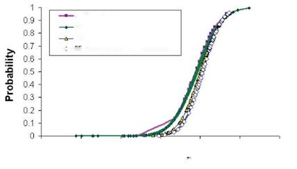
The effect of sample size on A – and B-basis predictions is presented in Figure 10 for the quasi-isotropic laminate under tension loading. MS-PFA was used to generate 55, 100 and 1000 samples. The predictions improved with the use of increased number of samples as compared to the 21 physical tests reported in reference [7]. The A and B – basis values for different random sample size are listed in Table 10. The randomly generated samples were fitted to normal distribution. Evaluating these virtual samples with STAT-17 yielded the A – and B-basis values presented in Table 10. As more virtual samples were generated, the mean value approached the real mean from the 21 physical tests. Data presented in Table 10 establishes confidence in the computational approach, especially to the stability of data obtained from virtual simulation. Next, validation of allowables for IM7/MTM45-1 with reduced testing is presented and discussed.
|
|
|
|
|
|
|
|
|
|
|
|
|
|
|
|
 |
|
|
![]()
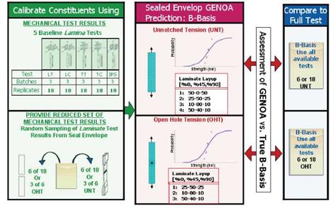
difference in the B-basis results obtained from prediction and those from current practices ranged from -5.31% and 5.34%. Figure 11 shows the steps followed to compute B-basis values for the various coupons starting with a reduced number of test replicates. The number of replicates varied from 3 to 6 as listed in Table 11. The same table compares MS – PFA B-basis predictions to those obtained using traditional methods and all available replicates [9-10]. The B-basis values from the references were not made available until after computational allowables were derived. The B-basis predictions were obtained with MS – PFA using a unique set of prescribed uncertainties of the following random variables: fiber tensile strength, matrix tensile strength, matrix shear strength, fiber volume ratio, and void volume ratio. The uncertainties were derived from the lamina level testing for IM7/MTM45 Open hole tension (OHT) coupon simulations showed errors in predicted mean tensile strength ranging from -12.7% to 8.88% compared to true average from test. The difference
|
Coupon Type |
Lamina |
B-basis (ksi) |
B-basis (ksi) |
Difference |
|
Un-Notched Tension RTD |
Proportions |
MS-PFA |
CMH17 [2] |
w. r.t. [2] |
|
[50-0-50] |
156.22 |
1 58.54 |
-1.46% |
|
|
[25-50-25] |
112.98 |
119.32 |
-5.31% |
|
|
[10-80-1 0] |
69.09 |
65.59 |
5.34% |
|
|
Un-Notched Compression RTD |
[50-40-1 0] |
173.41 |
178.4 |
-2.80% |
|
[25-50-25] |
59.4 |
62.15 |
-4.42% |
|
|
[10-80-1 0] |
41.59 |
41.67 |
-0.19% |
|
|
[50-40-1 0] |
98.13 |
1 00.63 |
-2.48% |
|
Table 11. Un-Notched and Notched B-Basis Strength Predictions for IM7/MTM45 (Tension Loading) |
|
|
|
(a) Damage initiation due (b) Damage growth imder (c) Fiber tensile failure at ultimate load to matrix cracking increased loading |
Fig. 12. Damage Initiation, Damage Growth and Fracture in Quasi OHT Made from IM7/MTM45 (Red Indicates Material Damage)
between simulation and test averages were addressed using Bayesian statistics update where CDF from simulation was corrected with the 6 few tests that were available. Animation of damage at the initiation stage and progression up to ultimate failure for the quasi open hole coupon under tension loading is presented in Figure 12. MS-PFA [4] identified critical damage evolution events isolating plies and elements contributing to the failure.
A – and B-Basis Validation for Open Hole Tension (OHT) T300/PPS Thermoplastic
To further demonstrate the validity of the MS-PFA approach for determination of allowables with reduced testing, A – and B-basis predictions were made for an open hole specimen under tension loading [11,12]. The specimen was fabricated from T300 carbon PPS thermoplastic composite material in a woven configuration with [±45/(0/90)]3S layup. First, MS-PFA was used to reverse engineer the constituent properties from lamina level LT, LC, TT, TC and IPS tests. Second, uncertainties in fiber and matrix properties and fabrication parameters were assumed since lamina level statistics for the T300/PPS material were not available. Unknown COV’s can be obtained from existing databases of comparable or similar materials or from experience based on anticipated scatter. Table 12 lists the
|
Test# |
Failure Load |
Test # |
Failure Load |
|
1 |
0.9218 |
16 |
1.0008 |
|
2 |
0.9507 |
17 |
1.0027 |
|
3 |
0.9593 |
18 |
1.0027 |
|
4 |
0.9690 |
19 |
1.0065 |
|
5 |
0.9709 |
20 |
1.0065 |
|
6 |
0.9728 |
21 |
1.0065 |
|
7 |
0.9853 |
22 |
1.0143 |
|
8 |
0.9853 |
23 |
1.0143 |
|
9 |
0.9892 |
24 |
1.0268 |
|
10 |
0.9950 |
25 |
1.0287 |
|
11 |
0.9950 |
26 |
1.0335 |
|
12 |
0.9960 |
27 |
1.0335 |
|
13 |
0.9979 |
28 |
1.0393 |
|
14 |
0.9979 |
29 |
1.0470 |
|
15 |
0.9998 |
30 |
1.0510 |
|
Table 12. Normalized Tensile Failure Load for T300/PPS Open Hole Composite Coupon |
|
Property |
COV |
|
Fiber longitudinal modulus |
5% |
|
Fiber longitudinal tensile strength |
5% |
|
Matrix modulus |
5% |
|
Matrix tensile strength |
5% |
|
Matrix shear strength |
5% |
|
Fiber volume fraction |
5% |
|
Void volume fraction |
5% |
|
Table 13. Random Variables Used in Predicting A – and B-Basis Allowables for T300/PPS |
normalized failure load from the test for the OHT case. The range of the failure load varied from 0.9218 to 1.051 with a standard deviation of 0.028. Table 13 lists the assumed random variables for use in the prediction of allowables. Initial COV of 5% was assumed for all random variables.
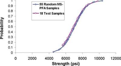
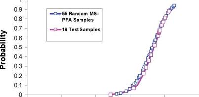
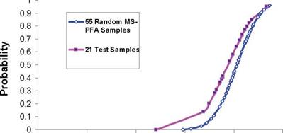
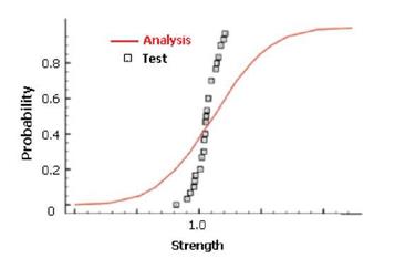
MS-PFA was used in conjunction with probabilistic analysis to replicate the scatter in the failure strength for the OHT coupon. The random variables were selectively perturbed by the analysis engine to populate enough data to predict the cumulative distribution of the failure stress. As indicated in Figure 13, the scatter from simulation did not agree with that from test when a coefficient of 5% was applied uniformly to all random variables. However, reducing the coefficient of variation to 1% for the fiber and matrix stiffness and strength and the fabrication variables, yielded an excellent agreement with test (Figure 14). If test data did not exist to calibrate the COV’s of the constituent properties and fabrication parameters, one can assume a 5% value as a starting point. Sensitivity analysis can also be used to reduce the list of random variables to include those that are very influential (those with sensitivity higher than 10%).
|
|
|
Fig. 14. Comparison of Scatter from Simulation and Test for T300/PPS OHT Strength With a Coefficient of Variation of 1% |
Processing the 30 test data through STAT17 resulted in an A-basis value of 0.92 and a B- basis value of 0.9486 with respect to a mean normalized strength of 1.0. The CDF obtained from MS-PFA resulted in A-basis value of 0.9104 and a B-basis value of 0.959 when the strengths were retrieved at the 1/100 and 1/10 probabilities. The maximum error from the prediction with respect to test was 1.1% as shown in Table 14.
Test (Mil-HDBK) Analysis % Error
A-Basis 0.92 0.9104 1.04%
B-Basis 0.9486 0.959 -1.10%
Table 14. Open Hole Tension Case Comparison of A- and B-Basis Values from Test and Analysis
Determination of A-Basis Values from B-Basis
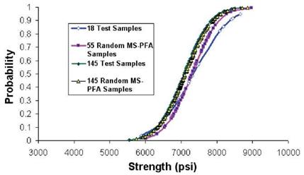
As discussed earlier, accepted standards for determination of A-basis require physical testing of 55 specimens from 10 batches (as a minimum). Reference [13] listed strength data from testing of 145 specimens for 90° tension laminate made from T700 fibers and 2510 epoxy matrix. The MS-PFA approach was used to generate random samples to determine A – basis for the transverse tension laminate assuming only 18 test samples existed. Note that the 18 specimens is the minimum accepted standard [1,2] for B-basis determination. The 18 test specimens were obtained from a total 3 batches from [13], the data extracted were the first 18 test points reported in reference [13]. MS-PFA was then used to simulate the scatter for the 18 specimens and used to generate additional samples (55 and 145 random samples). The virtual test samples generated by MS-PFA used the statistics listed in Table 15.
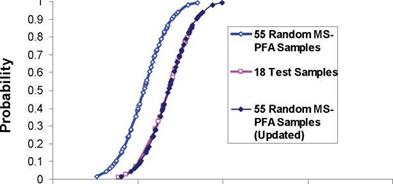
Figure 15 shows a plot of the 18 test samples, 145 test samples, and 55 and 145 MS-PFA virtually generated test samples. The MS-PFA virtual samples fitted the 145 samples from physical test with great accuracy. The technical approach in MS-PFA can be used to generate virtual test samples not available thru physical testing. This is evident by the goodness of fit between simulated and test data and with the accurate calculation of A – basis as presented in Table 16.
|
Property |
Mean |
COV |
Distribution |
|
Ef11 (msi) |
34.80 |
5.00% |
Normal |
|
Sf11T (ksi) |
604.50 |
7.56% |
Normal |
|
Sf11C (ksi) |
366.90 |
6.15% |
Normal |
|
Em (msi) |
0.53 |
5.00% |
Normal |
|
SmT (ksi) |
11.62 |
8.39% |
Normal |
|
SmC (ksi) |
46.00 |
4.73% |
Normal |
|
SmS (ksi) |
37.82 |
2.82% |
Normal |
|
FVR |
0.53 |
2.50% |
Normal |
|
VVR |
0.03 |
2.50% |
Normal |
|
Table 15. Random Variable Statistics for Determining A-Basis Strength from B-Basis for T700/2510 90° Tension Laminate
|
|
Fig. 15. Comparison of 18 and 145 tests to 55 and 145 MS-PFA Virtual Samples Used in Determining A-Basis Strength from B-Basis for T700/2510 90° Tension Laminate
|
The referenced table lists A – and B-basis calculations obtained using the data from test and simulation after running STAT-17 with the generated virtual test samples. For each random sample generated, MS-PFA is executed to determine sample failure stress. Table 16 also lists the mean strength from test and simulation. The mean strength value from 145 MS-PFA simulations was within about 0.5% of that from 145 physical test samples. The accuracy in predicting mean strength and A – basis values demonstrates the effectiveness of the devised methodology for determination of allowables with reduced testing.
3. Summary
A computational method has been presented for determining A and B-basis composite strength allowables with a significant reduction in testing over standard FAA and CMH-17 methods. The method combines multi-scale multi-physics progressive failure analysis (MS – PFA) with probabilistic methods and Bayesian updates. It was demonstrated for typical aerospace composite materials such as MTM45-1 145 AS4, IM7/MTM45-1, T300/PPS and T700/2510. Starting from lamina level coupon test data, root cause fiber and matrix properties, fabrication variables, and associated uncertainties are reverse engineered with MS-PFA for use in generation of strength allowables. MS-PFA is then used to virtually generate random laminate level test samples. In turn, the virtual test data are used to calculate allowable values for notched and un-notched composite laminate specimens.
The methodology is robust and can be easily inserted into material characterization and qualification programs to yield a significant reduction in the number of physical tests at the laminate level. Additionally, the approach can be relied on to generate allowables for configurations (layups) that were not initially included in a test plan as long as the simulation results are verified with few tests that are representative of the over-all design envelope. Very importantly, the methodology was validated for typical aerospace composite laminates and calculated A and B-basis values compared very well with test.

