For the visual appearance of a synthetically generated image, it is important to determine how far the applied methods for the approximation of the light distribution are adequate for the data to be generated. While rendering of the surfaces of the tree skeletons with the already-mentioned local and global lighting procedures is achieved satisfactorily, the leaves and small petioles must be generated with different methods.
As already mentioned, a leaf is translucent. If it is held against a light source, such as a lamp, the light shines through remarkably softly. This effect is caused by the diffusion of the light inside the leaf, where many small particles of varying optical density diffract the light rays. Similar effects are created when light hits marble, skin, or snow.
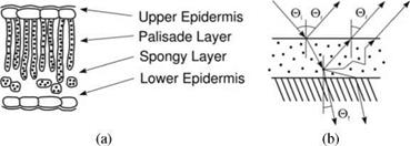
Incident light is either reflected by the leaf surface or penetrates the leaf interior. The light is diffused by small particles, such as pigments, it may either be absorbed or transmitted back through the upper or lower sides of the leaf. The situation becomes even more complicated: a leaf consists of several layers, which each have their own optical characteristics.
In Fig. 9.5b, the scattering process is illustrated in the two top layers of a leaf. Light hits the leaf surface at angle 0* and is partially reflected directly at an angle 0r. Another part of the light enters at angle 0′ into the leaf and is either diffused or absorbed. At the border of the next layer, the light is again diffused and enters at angle 0t the next layer. Another part is reflected towards the
surface and is reflected at angle 0r. The two angles 0r and Qt are here not fixed, but instead there is an entire angle area throughout which the light is diffused.
In the sense of Eqn. (9.5), the BRDF, which describes the reflecting attributes of a leaf, must be supplemented with an appropriate transmission function, the BTDF: a ray hitting the leaf surface is changed by the BTDF in its strength and can be perceived on the lower side of the leaf. Consequently, the integration area in Eqn. (9.5) must be expanded from the hemisphere to all spatial directions.
|

The BRDF and BTDF are together abbreviated as the BDF which describes, in relationship to the angle (now 360°), the amount of the emitted light. The BDF can be measured for real leaves and the data can be applied for the rendering. This was demonstrated in a number of optical experiments using leaves of different plants (see [96]).
In addition to the quantity of light dispersed into a certain direction, the spatial conditions are also of importance; in particular, the distance the light travels inside the leaf before being reflected back is responsible for the soft effect at the surface. The basis for the computation of such subsurface scattering inside objects with different layers is described by Hanrahan et al. [82]. Using this source, Jensen et al. [101] developed a practically applicable model. They reduced the needed computation to a direct reflection and another term, that per each hitting light ray added a diffuse light source with a limited effective radius.
![]() In a special analysis for leaves, Baranoski and Rokne [8] use an abstracted leaf model that is shown in Fig. 9.5a. Four layers determine here the optical characteristics. On the leaf surface the light enters into the epidermis. The color-producing layer, the mesophyll, lies directly below. The cells within the mesophyll have cylindrical form and are surrounded by air. This is also true for the layer further down, which consists of small round cells, the chloroplasts, that also are surrounded by air spaces. The last layer, the lower epidermis, seals the leaf.
In a special analysis for leaves, Baranoski and Rokne [8] use an abstracted leaf model that is shown in Fig. 9.5a. Four layers determine here the optical characteristics. On the leaf surface the light enters into the epidermis. The color-producing layer, the mesophyll, lies directly below. The cells within the mesophyll have cylindrical form and are surrounded by air. This is also true for the layer further down, which consists of small round cells, the chloroplasts, that also are surrounded by air spaces. The last layer, the lower epidermis, seals the leaf.
The optically important properties are here the leaf surfaces (Boundary 1), the boundary between the mesophyll and the air field (Boundary 2), between the air space and the lower epidermis (Boundary 3), and on the lower epidermis (Boundary 4). At each boundary, the light is directed dependent on the diffraction index пі of the medium from which the light originates (at the first bound-
Chapter 9 ary, the air), and that of the second medium nt, into which it penetrates. The Rendering so-called Snell’s law is written as
Пі sin ©i = nt sin ©t, (9.8)
where, again, ©i is the angle in the first medium and ©t is the light angle in the penetrated second medium. The ratio of the reflected light is determined by the Fresnel coefficient F є [0… 1], which is written in a simplified form as
F = (пі – nt)cl + (cos©Ї – cos©t)nl (9 9)
(cit (ni + n2) + nit (cos ©2 + cos ©2))2 , .
with
Cit = cos©i cos ©t, nit = mnt. (9.10)
A ray directed by raytracing is, dependent to a random value being above F, either reflected or directed into the adjacent medium. If its path length in the respective medium is above a given length, it will be absorbed.
Absorption and reflection behavior depend on the material properties of the leaves. For instance, the epidermis can be described by a number of adjoining ellipsoids, which determine the reflection properties through their form. If the ellipsoids are flat, then the leaf, for example, has a larger specular reflection ratio.
Actually, the global absorption is determined by the thickness of the leaf in combination with the concentration of pigments and their absorption coefficients. In sum, with the calculation indications of the layers, their thicknesses and the concentration of the pigments, as well as the flatness of the ellipsoids of the epidermis, a sufficiently accurate simulation model for the light distribution can achieved. The computed curves comply well with the measured values of the already-mentioned experiments, although an application of the method in current rendering has not yet been implemented.
 Figure 9.6
Textures used for rendering leaves:
(a) adaxial diffuse reflection;
(b) abaxial diffuse reflection;
(c) translucence; (d) alpha channel;
(e) thickness; (f) extinction;
(g) bump map
(a) (b) (c) (d) (e) (f) (g)
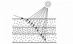
On the other hand, a simplified raytracing model on the basis of the approximation presented by Jensen et al. [100, 101] makes it possible to achieve good results with an approximate scheme. In a preprocessing step a number of textures are obtained. These are photographs of the upper and lower leaf sides as well as a throughlight image obtained by scanning the leaf in a corresponding
 scanner. This image is used for modulating the leaf’s throughlight behavior. The textures are then computed from these three source images (see Fig. 9.6). The raytracing algorithm for rendering the leaf works according to the following scheme: if the virtual observer is on the same side of the leaf as the light source, the corresponding texture for the reflection is used and the intensity is computed according to the algorithm below (see also Fig. 9.7).
shadow rays
traced ray
Boundary 1
|
|
|
|
|
|
|
|
|
|
|
|
|
|
![]()
If the leaf is located between the viewer and the light source, we do not distinguish from which side the leaf is viewed; in both cases the tranclucence is computed in the same way according to the optical measures, which do not show any significant differences here. The algorithm can be written as follows:
for each ray through do begin
obtain thickness and extinction value from maps alter surface normal according to bump map for each of the three layers do begin refract ray at border of layer compute step width from current thickness value according to [101] for each step through volume do begin for each light source do begin
compute light path length inside the leaf reduce light intensity exponentially according to path length and extinction value
if light source and viewer are at same side of leaf
then modulate value by front – or backside texture resp. else modulate value by throughlight texture
end
end
end
for each light source do begin
add multiscatter term as an ambient factor (if necessary) if light source is on the same side as viewer then add specular term
end
end
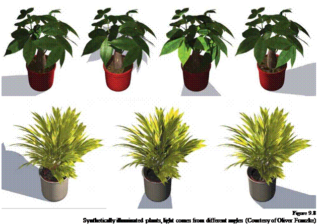
Chapter 9 As mentioned above, this is a simple but efficient variant of the algorithm of Rendering Jensen et al. [101] for rendering leaves. Figure 9.8 shows a synthetic plant with

varying light positions. In Fig. 9.22 a similar technique based on a standard lighting algorithm is used, the image appears realistic because of the proper use of specular reflection and translucency.


