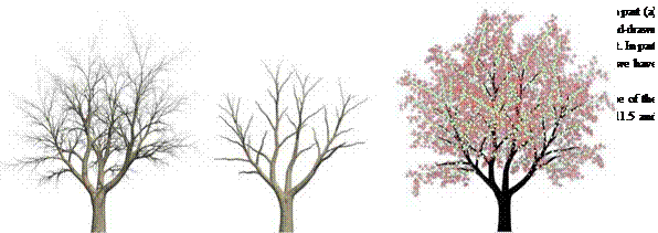
As discussed at the beginning of this chapter, in the past diverse attempts were made in which trees were illustrated as skeletons with a number of different objects representing the leaves or leaf clusters.
This idea can be generalized with the introduction of so-called “abstract drawing primitives”. These are polygons always facing the viewer, similar to the already-discussed billboards. The polygons reflect here an outline of a leaf or of a group of leaves. The drawing of the entire tree then consists of a drawn version of the tree skeleton and the appropriate rendering of these primitive objects.
For the variation of the detail, which was identified as an essential forming element, depth buffers are used analogously to the works of Saito und Takahashi. They determine which part of each of the primitives should be drawn. However, the decayed form of the foliage and the corresponding unsteady structures in the depth cannot be processed by applying depth derivatives of first and second order, since in this case too many lines would be created. Instead, simply the depth differences are analyzed.

 As a starting point for the drawings, realistic tree geometries are used that can be generated with the already-introduced methods. Aside from the applicability of the existing models, here another advantage results: with the appropriate selection of abstract drawing primitives, a correlation between a sketched tree and a photorealistic rendition can be produced. This is useful in an animation when a transition is desired for artistic reasons, or in the course of a design process when the status of the planning should be visualized using the realism of the illustrated models. An additional advantage is that the complete three-dimensional information can be used, and, thus, the correct shading of the models is possible.
|
|
|
|

Tree II Tree III
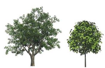
Chapter 11 Figure 11.9 shows some models for which the synthetic illustration is to be
Landscape Sketches analyzed. Tree I is a larger tree that is used to demonstrate whether the method
is appropriate for realistic complex models, tree II was selected as an example for a smaller, detailed tree to be drawn, while tree III is used as a representative of a pine tree.
The tree geometries are divided into two parts for further processing: the tree skeleton and the foliage. The latter is only represented with the position and the surface normal of the leaves; all geometry information is deleted. In this way the already-discussed abstraction is implemented.
 |
However, it is not necessary to process the very detailed information provided by the realistic tree models, if later on they are to be represented by solely a few lines. If for relatively abstract illustrations only a few, but large primitives are required, then the number of leaf positions in the initial model can be decreased accordingly. This takes place either manually in the modeling program or through an automatic level-of-detail (LOD) mechanism in the rendering program for tree geometries.
Figure 11.10 Data used for the processing of tree models: (a) tree skeleton; (b) thinned out tree skeleton; (c) leaf positions, the varying colors mark points of different geometric resolution
drawing of the foliage
The polygons that are used as drawing primitives are joined to the leaf positions in the tree, and are aligned according to the viewing direction. A number of drawing styles can be achieved with disks or randomly aligned ellipsoids. Additional candidates that function as representatives for whole clusters of leaves are leaf-shaped polygons or also jagged larger circle type disks, similar to the drawings in the children’s books at the beginning of this chapter.
The algorithm works in two steps: in the first step the primitives are drawn according to their position in the tree, whereby through the depth buffer of the hardware hidden parts are eliminated. The polygons are closed, their surface will be drawn in white, and their contours with black color.
The result is a very detailed clustering of primitives similar to Figs. 11.5a or 11.7b-c. To achieve fewer details, in the second step it becomes necessary, in addition to the elimination of occluded surfaces, to further delete parts. This process is executed using the depth-difference algorithm.


