1.1 Case study
The proposed approach has been carried out considering as case study an aeronautical component. This is a winch arm mounted on an helicopter (see Fig. 2). The winch arm is the external unit that allows the helicopter to rescue people or things where it is impossible to land through a rope lowered by an electrical motor.
The winch arm have a main arm and a head covered by three thin fairings.
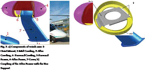
On the main arm (the part with number 1 in Fig. 3a) are assembled two frames (the yellow parts 5 and 6 in Fig. 3a) that are two cambered elements connecting and supporting all the structure. The parts with number 5 and 6 in Fig. 3a are the forward and the after internal frames that allow to mount the fairing covers of the head (parts 3 and 4 in Fig. 3a) of the winch arm directly on its structural beam. Finally, the Mid Cowling (part 2 in Fig. 3a) is the central exterior fairing that covers the head of the winch arm The part 7 in Fig. 3a is a cover for the overhaul of the winch arm. All the components of the winch arm assembly are made in carbon fiber composite material. Both of the frames are made with five layers of carbon fibers imbued in a matrix of epoxy resin for a total stack thickness of 1,65 mm. The carbon fibers are oriented in a ± 45° alternated arrangement within a steel cast which reproduces the part. After the stratification process, a curing process is carried out by autoclave with a control of temperature and pressure. The obtained part has size of 300 mm x 400 mm x 500 mm.
The weight of each part is about 350g. Assembly operations among the parts are done using of special grub screws that are inserted in the holes of each component. No adhesives or resins are used to secure the surfaces, since a perfect adhesion is not required.
Even if the form of the frame may appear simple, the shapes of its surfaces aren’t regular. The After Frame is coupled to a metallic part, called Box Support, that allows to fix the engine of the winch arm (see Fig. 3b).
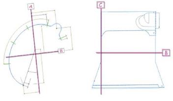
Each part has three datum planes as component references. Those planes are external to the part geometry, as shown in Fig. 4 for the Mid Cowling (dimensions and tolerances are not
reported in this chapter, since they are reserved). The nominal location and tolerances of coupling holes are defined as regards to this external reference frame. Profile tolerances are defined as general requirements for the whole assembly by the manufacturer. The value declared is ±0.75 mm. In this case form errors may have effect on the airflow around the head of the winch arm.
Furthermore, the parts may have a significant geometric distortion after removal of the forces applied during fabrication. This is a characteristic of composite laminates and occurs as soon as the stratification cast is removed. This is due to its low thickness, weight, flexibility and to the release of internal stresses resulting from the manufacturing processes. When the manufacturing process is completed all the references to the nominal configuration are lost. In order to re-obtain the nominal shape it is necessary to apply forces able to win the elastic recovery of the part. This problem is present during the assembly of the Mid Cowling with its mating components.
 |
Further applications of the proposed method may be found in (Polini et al., 2007; Marziale & Polini, 2008).
|
Fig. 4. Datum planes of the Mid Cowling |


