The complexity of the wing shape required the production of the knitted preform on a flat weft knitting machine, due to their advantages mentioned before.
The preform was knitted on a CMS 320 TC Stoll machine, using EC 11 408 Z28 T6 (Vetrotex) glass fibre. The yarn was tested on a Housenfield (Tinius Olsen) testing machine model H100 KS in order to determine its mechanical properties. The yarn is characterised in chapter 2 of this work.
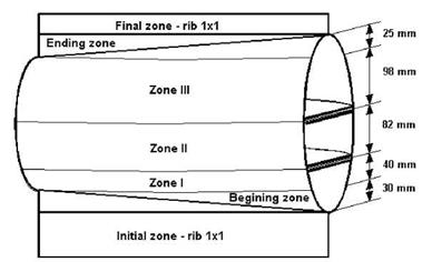
The production of a preform that includes the inner walls requires a sandwich structure with connection through single knitted layers, according to the dimensions defined above. A very important aspect is the knitting direction that is determined in this case by the position of the inner walls. In the preform, the inner walls are created by the connecting knitted layers. Choosing another knitting direction, perpendicular to the one considered is not a viable solution due to the fact that this way the inner walls (connecting layers) are impossible to knit. Fig. 33 illustrates the architecture of the knitted preform. The zones marked on the drawing represent:
• border – 1 x 1 rib on selected needles;
• initial zone -1 x 1 rib – this is the part where the rib evolution is produced on all needles and the feeder for the glass yarn is not yet working; it is subsequently removed, together with the border;
• beginning zone – first zone in the preform, corresponding to its inclined inferior extremity;
• zone I – zone made only of the outer fabrics up to the first inner wall (connecting layer);
• zone II – zone of the outer fabrics between the inner walls;
• zone III – zone of the outer fabrics up to the beginning of the inclined superior extremity;
• ending zone – zone corresponding to the superior extremity.
|
Fig. 33. Architecture of the knitted preform |
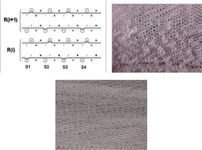
In the case of the considered knitted sandwich structure, both the outer fabrics and the inner walls are knitted on selected needles (1×1). A tubular evolution on selected needles with fleece yarns can be used in order to increase the fabric compactness (see Fig. 34). The main problem with last structure is the positioning outside the fabric of the floating fleece yarns that generates an irregular plush aspect, and also increases the snagging. Still, the simple pretension of the fabric, specific to the production of the composite material eliminates this situation.
|
Fig. 34. Tubular evolution on selected needles with fleece in-lay – fabric aspect relaxed and stretched |
Table 6 presents the values of the main structural parameters for the two structures (simple tubular on selected needles and tubular on selected needles with fleece yarns).
|
Structure |
Stitch density |
Stitch pitch A, [mm] |
Stitch height B, [mm] |
Stitch length ktitch, [mm] |
Weight M/m2, [g] |
||
|
Dw [wales/50mm] |
Dr [rows/50mm] |
||||||
|
Tubular, on selected needles |
16 |
26 |
3.12 |
1.92 |
9.6 |
842 |
|
|
Tubular, on selected needles, with fleece yarns |
12 |
25 |
4.17 |
1.92 |
10.3 |
4.7 |
950 |
|
Table 6. The values of the main structural parameters for the knitted fabrics |


