The DCB specimen, as shown in figure 5, is made of an isotropic fibre-reinforced laminate containing a thin insert at the mid-plane near the loaded end, L =250 mm, w =25 mm and h =1.5 mm, was analyzed by Moshier (Moshier, 2006). The initial crack length (lc ) is 34 mm. A displacement rate of 650 mm/sec is applied to the appropriate points of the model. Young’s modulus, density and Poisson’s ratio of carbon fibre-reinforced epoxy material are given as E =115 GPa, p =1566 Kg/m3, and и =0.27, respectively. The properties of the DCB specimen interface are given as following: GIC = 0.7 kJ/m2, Ko = 1×10⁵ N/mm3, Kmln = 0.333×10⁵ N/ mm3, Jo = 50 MPa, and CTmln = 16.67 MPa
Similarly, the LS-DYNA finite element model consists of two layers of fully integrated S/R 8-noded solid elements, with 3 elements across the thickness. The adaptive rate-dependent cohesive zone model is implemented using a user defined cohesive material model in LS – DYNA. Two different values of viscosity parameter are used in the simulations; n = 0.01 and 1.0 N-sec/mm3, respectively. Note that n is a material parameter depending on deformation rate, which appears in equations (1) and (11). When n =0, it would be a traditional model without rate dependence. By observing equation (1), n determines the ratio between viscosity stress ц5т and interface strength Jm since Jm = <Ji if equations (1) and (4) are considered by setting K = K . For example, if Sm = 6.5 mm/sec is assumed on the interface here (i. e. 1% of loading rate). n = 0.01 N-sec/mm3 corresponds to a low viscosity stress of 0.065MPa, which is much lower than the initial interface strength of 50 MPa. However, n =1.0 N-sec/mm3 corresponds to a viscosity stress of 6.5 MPa, which is around 13% of the interface strength, and denotes a higher rate dependence. In addition, two sets of simulations are performed here. The first set involves simulations of normal (bilinear) cohesive model. The second set involves simulations of the new adaptive rate-dependent model.
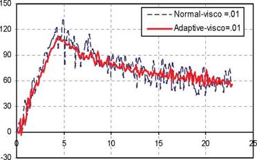
A plot of a reaction force as a function of the applied end displacement of the DCB specimen using cohesive elements with viscosity value of 0.01 N-sec/mm3 is shown in figure 14. It is clearly shown from figure 14 that the bilinear formulation results in a severe instability once the crack starts propagating. However, the adaptive constitutive law is able to model the smooth, progressive crack propagation. It is worth mentioning that the bilinear formulation might bring smooth results by decreasing the element size.
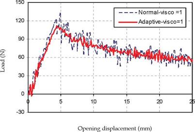
The load-displacement curves obtained from the numerical simulation of both bilinear and adaptive cohesive model using viscosity parameter of 1.0 N-sec/mm3 is presented in figure 15. It can be seen that, again, the adaptive constitutive law is able to model the smooth, progressive crack propagation while the bilinear formulation results in a severe instability once the crack starts propagating. The average maximum load obtained using the adaptive
rate dependent model is 110 N, whereas the average maximum load predicted form the bilinear model is 120 N.
|
|
Opening displacement (mm)
|
Fig. 14. Load-displacement curves obtained using both bilinear and adaptive formulations (П = 0.01)
|
|
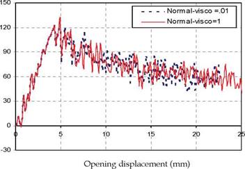
Fig. 16. Load-displacement curves obtained using bilinear formulations (n = 0.01,1) |
|
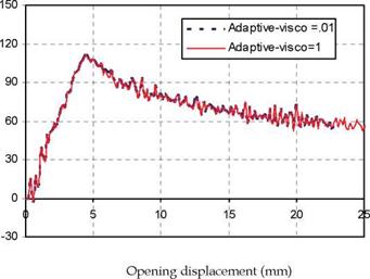
Fig. 17. Load-displacement curves obtained using adaptive formulations (n = 0.01,1) |
Figure 16 shows the load-displacement curves of the numerical simulations obtained using the bilinear formulation with two different viscosity parameters, 0.01 and 1.0 N-sec/mm3, respectively. It is noticed from figure 16 that, in both cases, the bilinear formulation results in severe instabilities once the crack starts propagation. There is a very slight improvement to model the smooth, progressive crack propagation using bilinear formulations with a high viscosity parameter. On the other hand, the load-displacement curves of the numerical simulations obtained using the new adaptive formulation with two different viscosity parameters, 0.01 and 1.0 N-sec/mm3, respectively, is depicted in figure 17. It is clear from figure 17 that the adaptive formulation able to model the smooth, progressive crack propagation irrespective the value of the viscosity parameter. More parametric studies will be performed in the ongoing research to accurately predict the effect of very high value of viscosity parameter on the results using both bilinear and adaptive cohesive element formulations.
2. Conclusions
A new adaptive cohesive element is developed and implemented in LS-DYNA to overcome the numerical insatiability occurred using the bilinear cohesive model. The formulation is fully three dimensional, and can be simulating mixed-mode delamination, however, in this study, only DCB test in Mode-I is used as a reference to validate the numerical simulations. Quasi-static and dynamic analyses are carried out in this research to study the effect of the new constitutive model. Numerical simulations showed that the new model is able to model the smooth, progressive crack propagation. Furthermore, the new model can be effectively used in a range of different element size (reasonably coarse mesh) and can save a large amount of computation. The capability of the new mode is proved by the great agreement obtained between the numerical simulations and the experimental results.


