Marina Koledintseva1, Konstantin N. Rozanov2 and James Drewniak1
1Missouri University of Science and Technology, Missouri, 2Institute for Theoretical and Applied Electromagnetics, Russian Academy of Sciences, Moscow,
1U. S.A.
2Russia
1. Introduction
Non-conducting wideband absorbing materials are important for improving immunity of electronic equipment and solving various problems of electromagnetic compatibility (Celozzi et a!., 2008). Application of absorbing materials for the design of shielding enclosures, coatings, gaskets, or filtering patches is preferrable compared to metal structures for several reasons. Typically enclosures of electronic equipment are made of highly- conducting metal to achieve the required shielding levels (Neelakanta, 1995). However, requirements to make electronic devices of smaller size and weight neccessitate substitution of metal by electrically conducting composites (Sichel, 1982) and polymers (Fox et al., 2008; Wang & Jing, 2005). Moreover, if a conducting surface has sharp edges, slots, and apertures, currents on this surface may drive unintentional antennas and enhance noise coupling paths as culprits of undesirable emissions (Paul, 2006). One of the ways to eliminate this problem is to use absorbing materials, including applications of magneto-dielectric composite materials for electromagnetic shielding purposes.
Engineering of absorbing materials with desirable frequency responses and advanced physical properties is of great importance. These materials can be either bulk or sheet, and, depending on a particular application, they may be shaped as needed. Frequency characteristics of composite absorbing materials may be either wideband, or frequency selective. The materials of interest should provide the required attenuation of surface currents on the extended conducting surfaces, and/or satisfy requirements on damping electromagnetic near-fields of the sources, or far-field electromagnetic waves of the given configuration, direction of incidence, and polarization. Advanced physical, chemical, and mechanical properties of absorbing materials are of great importance as well. The materials must comply with requirements on thermal, chemical, and mechanical stability and durability, incombustibility, non-toxicity, environmental friendliness, and adhesion with surfaces on which they will be placed.
It is important that when applied to electronic products, the engineered absorbing materials would allow for compliance with requirements and regulations from the point of view of
 |
|
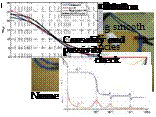
 electromagnetic compatibility (EMC), electromagnetic immunity (EMI), signal integrity (SI), and power integrity (PI) over frequency ranges of interest. For applications in high-speed digital electronic designs, the materials that would absorb electromagnetic energy in RF, microwave, and potentially mm-wave bands, are of special interest. The necessity of using absorbing materials becomes more and more important, since operating frequencies of electronic devices increase, package density grows dramatically, and the number of electronic equipment and devices of mass production continues to increase. Thin absorbing noise-suppressing composite sheets and coats are of special interest for such applications, especially because of microminiaturization trends and of convenience to apply directly on the surfaces to be protected, as well as their broadband performance. Some examples of applying thin sheet absorbing materials are shown in Fig. 1. Thin sheet absorbers can wrap cables, or be applied directly on the sources of noise, or at some optimal distance from the source. They can be put directly on the electronic module enclosure, around or over vents, holes, sharp edges, and wedges, or may be placed as patches inside cavities to damp unwanted resonances.
Fig. 1. Some examples of applying thin sheet absorbing materials
Also, electronic composites, whose properties can be controlled by thermal or electromagnetic means, play an important part in modern micro – and nanoelectromechanical systems such as sensors, filters, switches, and actuators (Taya, 2005). However, they will not be considered herein, since the specific topic of the present work is absorbing composites for electromagnetic waves and fields.
An absorbing, non-conducting composite material may contain conducting non-magnetic inclusions (e. g., carbon or non-magnetic metal particles) at concentrations below the percolation threshold as fillers in a dielectric host (matrix, base) material (Lagarkov & Sarychev, 1996; Sihvola, 1999; Tretyakov, 2003). Electromagnetic wideband radar absorbing materials may include conducting magnetic (e. g., iron or permalloy) powders (Birks, 1948; Merrill et al., 1999; Absinova et al., 2007) or combinations of granular ferrite and conducting particles, e. g., carbonyl-iron powders (Park, et al., 2000). Electromagnetic wave absorbers also widely use non-conducting soft ferrites with spinel structure, e. g., Ni-Zn, Ni-Zn-Co, or Mn-Zn ferrites (Naito & Suetake, 1971; Shin & Oh, 1993; Kazantseva et al., 2004; Lisjak et al., 2006), or hexagonal ferrites (Mikhailovsky et al., 1965; Ota et al., 1999; Iijima et al., 2000). Combining inclusions of different types (dielectric, conducting, and magnetic) in a multiphase composite material may yield substantial increase in the absorption level in the
desired frequency range. The absorbers can form either thick or thin films (paint) placed on the surfaces to be protected from unwanted radiation or coupling paths, or foam, as in anechoic chambers. The absorbing materials may form multilayered resonant structures, such as a Jaumann absorber or a Salisbury screen (Knott et al., 2004).
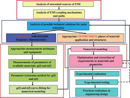
A current objective is to develop a methodology to efficiently design and evaluate novel products based on absorbing magneto-dielectric composite materials primarily for EMC/EMI purposes. Fig. 2 shows a flowchart for engineering design of noise-suppressing materials and electromagnetic filtering structures.
|
Fig. 2. Flowchart for engineering design of EMI noise-suppressing materials and structures |
The analysis starts from diagnozing and caracterizing sources of unwanted radiation and/or undesirable electromagnetic interference coupling paths and mechanisms. Then possible technical solutions to eliminate or minimize those noise effects are proposed and analyzed. Any technical solution is based on a combination of proper material (or materials) and geometry. This means deciding, where the chosen materials should be placed, and what their configuration should be to achieve the required noise reduction in the intended frequency and dynamic (power or field amplitude) ranges. If choosing an appropriate material among already existing – either available commercially, or specially synthesized in laboratory conditions, it is important to measure their electromagnetic properties. These are the complex frequency-dependent dielectric susceptibility Je(^) or permittivity £(u>) = and complex magnetic susceptibility jm(u>) or permeability = 1 + Хт(ы) in the frequency range of interest. Alternatively, a material is characterized by its dielectric and magnetic susceptibility kernels (e(t) and (m(t), which are the impulse responses corresponding to Xe(^) and Xmfa). There are different measurement techniques for evaluating electromagnetic properties of materials (Chen, 2004;). The choice of a specific measurement technique depends on the frequency range of interest, material type (dielectric, magneto-dielectric, or conductive; isotropic or anisotropic; linear or nonlinear; exhibiting narrowband resonances, or having comparatively flat frequency dependence in the frequency range of interest); instrument availability; required accuracy and repeatability. There are some other factors, for example, how time-consuming and resource-consuming those measurements are. Different methods of characterization of dielectric materials are summarized in (Von Hippel, 1995; Chen, 2004), and various approaches to extract parameters of ferrite materials over different frequency ranges are described in (Polder, 1950; Rado, 1953; Mullen & Carlson, 1956; Lax & Button, 1963; Korolev et al., 2008).
Currently there are numerous automated methods for wideband characterization of dielectric and magnetic bulk materials (Nicholson & Ross, 1970; Weir, 1974; Barry, 1986), as well as of thin films (Bekker et al, 2004; Booth et al., 1994). The existing techniques are typically based on various transmission/reflection measurements, either in the frequency domain, or in time domain, in transmission lines, cavities, open space, or using special probes terminated with material samples under test. The literature is replete with various measurement techniques (Nicholson & Ross, 1970; Fellner-Feldegg, 1972; Weir, 1974; Baker – Jarvis, et al., 1993, 2001; Musil & Zacek, 1986; Ghodgaonkar et al., 1990; Zheng & Smith, 1991; Ganchev et al., 1995; Jargon & Janezic, 1996; Wang et al., 1998; Roussy et al. 2004; Ledieu & Acher, 2003; Bekker et al., 2004).
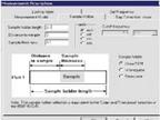
For practical EMC purposes, it is convenient to have systematic methodology to help EMC engineers to design and evaluate effectiveness of EMI noise-suppressing materials and structures based on their measured dielectric and magnetic responses. An overview of this methodology is presented in Fig. 3, corresponding to the flowchart in Fig. 2.
The dielectric and magnetic properties of the samples, depending on the measurement technique, are extracted either discrete frequency points, or over selected continuous frequency bands. Then the continuous frequency characteristics over the entire frequency range of interest can be restored. This is done using an appropriate curve-fitting technique. For further analytical and/or numerical modeling of structures containing dipersive materials, it is important that the resultant continuous material frequency dependencies would satisfy passivity and causality requirements over the entire frequency range of interest. Passivity means that the initially measured transmission and reflection coefficients in a passive system is in a physically meaningful range between 0 and 1 in unitless system, or fall below 0 in logarithmic units. Causality means that real and imaginary parts of complex permittivity £(o>) = £'(o>) — }е"{ш) and complex permeability ^ (o>) = ^'(w) — related through the Kramers-Kronig relations (Landau & Lifshitz, 1960; Lucarini et al., 2005), and, hence, no response could be obtained before a passive linear system has been excited by an external source. After the continuous causal complex functions £(o>) and ^ (o>) are obtained, they can be used in building either an analytical, or numerical electromagnetic model to predict effects of the absorbing material upon characteristics of the particular noise radiation and coupling scenario under study.
Validation of theoretically predicted or numerically simulated results is an important stage of the methodology. Creating an experimental test vehicle, which is suitable and comparatively simple for modeling, and at the same time captures the main features of noise generation, coupling physics, and attenuation by an absorbing material, is probably the most difficult and time-consuming task. Mutual correction and fine tuning of the experimental setup and a modeling prototype are always required at this stage.

 |
 Material parameter measurement Extraction of p and s parameters
|
|
Fig. 3. An EMC absorbing material design methodology
As soon as the agreement between measured and modeled results over the entire frequency range under consideration is achieved, the model and experimental setup may be subjected to some parametrical variations for developing practically useful design curves. Based on those design curves, applicability of the specific absorbing material in the particular practical scenario can be predicted. Different kinds of commercially available or new laboratory-synthesized materials could be compared with each other from the point of view of noise reduction effectiveness according to the imposed criteria, and the optimal solutions could be chosen.
2. Analytical model to predict frequency characteristics of a composite
Prediction of wideband frequency responses of effective electromagnetic parameters (permittivity and permeability), as well as concentration dependencies of composites, are important for engineering new electromagnetic absorbing materials. Herein, the general case of a magneto-dielectric composite material with either non-conducting ferrite, or conducting magnetic alloy inclusions in a dielectric polymer host, is considered. In addition, the composite may contain some fractions of non-magnetic conducting or dielectric inclusions. In the general case, each material phase may have its own frequency-dependent
permittivity and permeability, and the resultant homogenized material would also have a frequency dispersion of its effective dielectric and magnetic properties.


