The glare is a fibre-metal laminate; it is made of thin aluminium sheets with a thickness of 0.2-0.5 mm and fibreglass embedded in an epoxy matrix with a thickness of 0.125 mm and a nominal fibre volume fraction of 59%.
Fibres direction is related to the lamination direction of aluminium sheets; 0° or Longitudinal rolling direction (L) indicates that the fibres are placed in the direction of metal lamination, while 90° or Longitudinal-Transverse rolling direction (T) indicates that the fibres are oriented in transverse direction. Composite materials suffer a treatment in autoclave at high pressure and temperature. Mechanical properties of Glare depend on the characteristics of his constituents: aluminium and fibre, the most important properties are reported in table 2. Mechanical properties of the adhesive are negligible if compared with the characteristics of embedded fibres, but the contribution of the adhesive characterizes the laminate performance strongly (Robinson & Hodgkinson, 2000). It determines the force between metal and fibre layers and its detachment of the adhesive at the metal / fibre layer is one of the most frequent modes of laminate failure. The use of thin layers of aluminium (0.3 – 0.6 mm) can not consider the thickness effects, as regards individual aluminium layers, and the laminate in its entirety. The method called "Metal Volume Fraction" (MVF) and "Theory of mixtures", it can determine the glare properties (Vasek et al., 1997).
5.3.2 Experimental tests
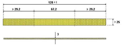
The specimens (Fig. 7) are made of fibreglass in the configuration quasi-isotropic [±30/ ± 90/±30]s but also reinforced with aluminium sheets 6061-T6 [+30/-30/+
90/aluminium/+90/-30/+30] (glare). The laminate thickness is 3 mm in the first case, 3.1 mm in the second case, and epoxy resin was used for both specimen types. Composite specimens are made of 12 fibreglass layers, while the glare is composed of 6 fibreglass layers and aluminium sheet in the middle.
Geometric characteristics of the specimens are presented in table. 3. The tests were performed with different values of imposed strain. The following "shift ratio" was used to characterize each tests:
![]() Rd = —
Rd = —
u
 |
It is similar to stress ratio R. All experimental parameters are known with knowledge of the value of maximum deflection and the length L between the two attacks.
|
|
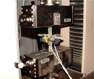
Fig. 8. Tensile test
Tensile tests were made to determine mechanical properties of both materials with Hounsfield material testing machine, equipped with proper grips for tensile test (Fig. 8). An extensometer was installed on the specimen to detect strains, while the load value is supplied by the load cell of 20000 N.
Static and fatigue tests were performed on different types of composite materials. All specimens are made of polyester resin and fibreglass, the vacuum bag technique was used. Table 4 shows the characteristics of the materials.
All specimens were loaded with a sinusoidal signal generated by the machine. It was operated at a frequency 3 Hz and was constant for all experimental tests. Also 10 load cycles were monitored to minimize the influence of any spurious signals for each acquisition. It was calculated the stress magnitude and then the mean is done and any anomalous points is eliminated.
|
Composite Materials |
Glare |
|
|
Thickness [mm] |
3.00 |
3.10 |
|
Width [mm] |
25.60 |
25.30 |
|
Height [mm] |
129.1 |
127 |
|
Arm [mm] |
67.2 |
67.2 |
|
No. layers |
12 |
7 |
|
Weight [g] |
17.2 |
22.6 |
|
Table 3. Geometrical characteristics of the specimens |
Filtering was done with a low pass filter downstream of the signal acquisition, to cancel the influence of noise, always present, even if of negligible value, obtaining the signal in Figure 9. Finally, the program shows the magnitude of each load cycles, a very important element in the early cycles, where it is possible to have a rapid damage of the material.
|
Material properties |
quasi-isotropic composite |
Glare |
|
fiber/resin |
Glass/polyester |
Glass/polyester |
|
direction fiber |
Equidirectional (60°) |
Equidirectional (60°) |
|
fiber volume fraction |
69.21 |
– |
|
MVF (Metal Volume Fraction) |
51.6 |
|
|
thickness [mm] |
3,0 |
3.1 |
|
longitudinal |
16357 |
38401 |
|
module[MPa] |
||
|
ultimate strength [MPa] |
303 |
s 200 |
|
Table 4. Material properties |
|
Fig. 9. Filtered signal (on the left) and monitored load (on the right) |
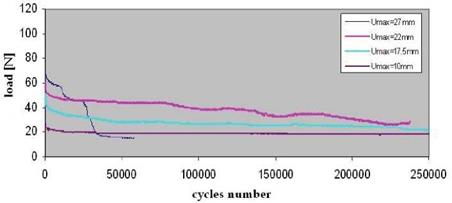
Fatigue tests were performed with different values of imposed strain, all characterized by pulse bending. The displacement ratio defined by 2 was zero since the minimum displacement was zero. So the position of minimum displacement is depicted in figure 3. Figure 10 shows load-number of cycles curves for almost-isotropic specimens, subject to pulsatory load with a maximum deflection (umax) from 10 to 27 mm. Figure 11 shows similar results for glare specimens.
|
|
|
|||
|
|||
|
|||
|
|
||
|
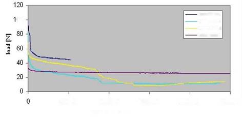

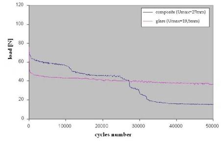
The behaviour of both materials is dependent on load highly. In fact there is a reduction of initial stiffness for small loads, and then a decrease of bearable load, which remains constant subsequently (Van Paepegem & Degrieck, 2002). During experimental test (i. e. for 500,000 cycles) glare specimens support a higher load than that of the quasi-isotropic composite, with a similar trend. Imposing greater displacements, the load trend is more variable than in the case of composite specimens. In composite specimens there is a damage step, indicating a gradual breaking of layers, for loads exceeding a critical value (60 N); while the glare can maintain a larger value of the load for long time, after an initial damage. This is due to the
presence of aluminium, which absorbs much of the load, leaving unstressed the glass fibres and allowing the specimen to maintain a non-negligible stiffness.
Figure 12 shows the degradation of specimens subjected to similar initial load. It shows as the glare presents a significant and unique collapse load, with few significant changes until the break; instead in the composite there is the sequential breaking of compressed fibres, with a step change of supported load. In all performed and analyzed tests there is always a localized damage in compressed fibres.

