The prepreg system used is a combination of G40-800 CF and 5260 toughened BMI resin made by CYTEC Co. The lamination has a quasi-isotropic (QI) stacking sequence, 32 plies [45/0/-45/90]^. The nominal thickness of 4.29 mm (0.134 mm x 32) was used in calculating stress on specimens. Laminate panels were cured in an autoclave at 190°C for two hours at a pressure of 6.0 kgf/cm2 and post-cured at 215°C for four hours in an air-circulating oven. All panels were cured at the same time.
(c) Common specimen for OHT and OHC static and fatigue tests Fig. 1. Specimen configurations for static and fatigue tests (mm)
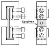
Fig. 1 (a) and (b) illustrate specimen configurations for NH tensile and compressive static tests. Fig. 1 (c) shows the configuration of OH specimens used for both static and fatigue tests. To avoid the complex stress state of coupon-type fatigue leading to failure in the vicinity of the clamping location, only OH specimens were used for fatigue tests. The
clamping parts of OH specimens were bonded with tubs made of the same material as the specimens. In the static tensile and tension fatigue tests, a longer clamp was used, while the static compressive tests, and compression fatigue and tension-compression fatigue tests used the shorter grip size shown in Fig. 1 (c). Laminate processing and specimen manufacturing were carried out at Kawasaki Heavy Industries, Ltd.
For generality, specimen configurations conform to ASTM standards or SACMA recommendations. Since the objectives of this study included the direct comparison of NH static and OH static strengths, the use of common OH specimens for comparing OH static and fatigue strengths, and specimen cost reduction, the specimen configuration shown in Fig. 1 (c) was employed. In particular, the cross-sectional area was equal for both NH and OH specimens. The hole diameter of OH specimens in this study was that from SACMA recommended methods, and other dimensions were smaller than those in the SACMA methods. Table 1 shows the number of specimens tested, with the number of run-out specimens for which the fatigue test was suspended given in parentheses.
|
Temperature (°C) |
Static test specimen |
Fatigue test, OH specimen |
|||||
|
NHT |
NHC |
OHT |
OHC |
R=0.1 |
R=10 |
R=-1 |
|
|
RT |
4 |
3 |
2 |
4 |
10(2) |
8 |
7 |
|
120 |
– |
1 |
– |
– |
– |
– |
– |
|
150 |
3 |
3 |
2 |
4 |
5 |
7 |
5 |
|
180, 215 |
– |
1 each |
– |
– |
– |
– |
– |
|
Number in ( ) represents run-out specimens Table 1. Number of specimens used for static and fatigue tests |
An INSTRON 8500 digitally-controlled servo-hydraulic material testing machine with an environmental chamber was used for static and fatigue tests. Static tensile tests for NH and OH specimens and static compressive tests for OH specimens were conducted using hydraulic grips. Static compressive tests for NH specimens were conducted using the NAL (National Aerospace Laboratory) type compression test fixture (Shimokawa et al., 1999-a, 1999-b, 2002) shown in Fig. 2. A supporting guide for both clamps seen in Fig. 2(a), which has a fine clearance to the top clamp, prevents moving of the clamps in the out of plane direction of the specimen. The test part of the specimen is not supported against out of plane bending. The compression load is given from both end-sections of the specimen. The actuator speed of the testing machine for all static tests was 1 mm/min.
Fatigue tests were conducted under sinusoidal constant amplitude loading with a repetition frequency of 1 Hz or 5 Hz. Three kinds of stress ratio, R=minimum stress/maximum stress, were selected, i. e., R=0.1 for tension fatigue tests, R=10 for compression fatigue tests, and R=-1 for tension-compression fatigue tests.
The temperature in the laboratory was controlled by an air conditioner at around 23°C throughout the year. Static and fatigue tests at high temperatures used an air-circulating environmental chamber (Shimokawa et al., 2007). Elevated temperature tests were mainly conducted at 150°C, as indicated in Table 1. For the static NH compressive tests only, several temperatures were chosen up to 215°C in order to estimate the effect of the heat-resistance of the BMI resin with respect to compressive strength. Stress in OH specimens in this study is represented by the net section stress,
where P is applied load, W specimen width, d open hole diameter, and t the nominal thickness of a specimen. Failed specimens were inspected visually and with a CCD microscope to determine the failure mode: fiber dominant or matrix dominant.
|
(b) Clamping assembly |


