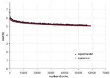
Experimental results are compared with those obtained by numerical simulations. The damage criterion has been implemented inside ANSYS code to evaluate current dimension of the defect varying the number of cycles; the mesh is implemented by square elements. External load is applied at the top of loaded layer; the constraints are placed in appropriate way to avoid axial tensions that change the ratio of mixed-mode failure.
 |
|||
Classic model (Sidoroff & Subagio, 1987; Van Paepegem & Degrieck, (a) 2001) for unidirectional composite fiberglass and epoxy resin (GLARE) subject to fatigue loads is applied, introducing the value of applied load instead of amplitude strain.
Stress and strain are linked together by the relationship:
^ = £0-(1 – D)-s (4)
Where E0 is the elastic modulus of non stressed material.
The parameter D is the variable of local damage, N the number of cycles, Aa is the amplitude of cyclic load applied, aTS is ultimate tensile strength of the material, A, Ъ and c are three coefficients depending on experimental material. Material constants are obtained by an optimization process applied to numerical simulation and the values are shown in table 7.
The analysis of damage propagation in hybrid composite specimens is carried out considering only the degradation of composite laminates and neglecting the damage of aluminum sheet. Below some experimental-numerical comparisons are showed for specimens with one and two aluminum alloy sheets (Fig. 26).
|
– і! |
|||
|
* experiment! • numerical |
|||
|
0 10000 20000 30000 40000 60000 60000 70000 80000 90000 number of cycles |
 |
Fig. 26. Experimental-numerical results for GLARE specimens for one (on the left) and two (on the right) aluminium sheet
Propagation under conditions of mixed mode of opening (MMELS), as widely described in literature (Blanco et al., 2006), is modeled by a power law type:
|
|
The following damage model is used in numerical analysis:
|
|||
|
|
||
|
|
||
|
|||
|
|||
![]()
![]()
The parameter a is the crack length, N the number of cycles, AG is available energy at the peak of the defect, Gcrit is the critical energy of the crack. The constants ci, c2, c3 are obtained numerically by an extrapolation process according to the performance of G-a (energy-crack length) that are assumed a pattern of exponential growth. It is then used a classic pattern (Model Stirling) to hypothesize the evolution of the crack growth.
ci =0,18 E (-2) c2= 0,21 c3=1,29
Fig. 27 shows some experimental-numerical comparisons.
|
Fig. 27. Experimental-numerical results comparison for MMELS tests |
6. Conclusions
During the project the machine is designed in very flexible way, choosing the load type, its size, its frequency, etc. So that fatigue tests on composite materials can be performed in operating conditions close to those of component in function. Analyzed specimens do not show subsidence or deformations after an initial visual inspection, but subsequent accurate observations show the presence (frequently) of the damage at interface between aluminium and composite layers.
Damage causes of a composite structure can be due to the application of fatigue loads (which determine the birth and propagation of cracks in sensitive areas) and the nucleation and propagation of interlaminar defects. These two types of damage can also coexist within structural element. Specimen damage after the initial phase of rapid growth tends to stop, this is due to the ability of redistribution of matrix-fibres composites to support stresses. Then it is essential to analyze the degradation mechanisms because the stresses that are created near a geometrical discontinuity could promote the delamination propagation or break of the layer of matrix. A severe obstacle to the spread of composites is their high sensitivity to defects and the degradation. The tests have allowed to study very well the damage evolution and so to estimate operating conditions of structural element after applying a certain number of fatigue cycles.
Experimental study of MMELS model for bonded joints is conducted to determine the damage before the phase of unstable crack propagation and shows that defect propagation occurs at the interface between adhesive and loaded layer (adhesive fracture) in MMELS model. The damage accumulated in adhesive coat during the loading history was marked. Load-number of cycles curve has a slight negative slope during fatigue load. Adhesive coat downstream from the apex of the defect accumulate some damage that alter the bending stiffness of the specimen. Unstable phase of crack growth follows at stable phase which rapidly spreads within a few cycles until final break of the component. A good correspondence between experimental and numerical results is found in all the analyzed cases both to composite laminates and to bonded joints.
The results show that the machine FTM setup is able to carry out its task with testing costs quite content. The extension to the bonded joints is particularly interesting.
Future developments: the optimization of the machine can be done by replacing the base with a more rigid and larger in order to have a second engine, more powerful, to perform tests that require higher loads, with an appropriate load cell. Also it is appropriate to consider the creation of a load cell for lower loads than 10 N, while eccentricity adjustment can be performed with micrometer spindle.


