The 3D knitted performs started to be developed in the ’90, mainly based on the development of electronic flat knitting machines and CAD/CAM systems. Even if there is significant progress in this domain, there are a lot of aspects that need addressed in order for the spatial knitted fabrics to become industrially feasible.
The spatial fashioning of the knitted fabrics is based on the need to produce fabrics with complex shapes that are similar to the shape of the final product. Even if a certain degree of spatial geometry can be obtained by using modules of structures with different patterns or by dynamic stitch length, the technique of spatial fashioning is the only one that has no limitations with regard to the shape complexity and dimensions. This technique (also known as ‘flechage’) is based on knitting courses on all working needles and courses on a variable number of needles, determining zones with different amount of stitches. The zones with the highest amount of stitches will have in the end a spatial geometry.
A classification of the spatial fashioned fabrics must take into consideration the 3D shape of the product, defined geometrically as a 3D body. These bodies can be divided in solids of revolution, such as tubes (cylinders), spheres and hemispheres, cones and frustum of cones, ellipsoids, hyperboloids, and polyhedrons, such as tetrahedrons, pyramids, parallelepipeds, etc. Apart from these simple bodies, other bodies can be considered: bodies obtained from composing simple bodies or bodies with irregular shape.
The fabric 2D plan is a rectangular area where are positioned fashioning lines that define the final 3D shape of the product. Such a 3D fabric is obtained by placing more fashioning lines with certain characteristics, forming repeating geometric basic forms within the plan or not (as is the case for parallelepiped forms).
 |
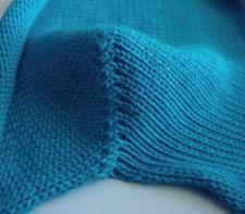 |
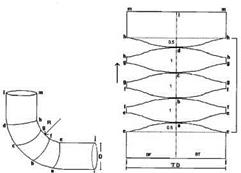
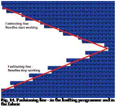
The fashioning lines can be defined as the zones where the knitting will be carried out on a variable number of needles, these zones generating the spatial geometry. The lines have two components, corresponding to decreasing the number of working needles and the other to increasing them. In the fabric, these two lines become one, the actual fashioning line, as presented in Fig. 14.
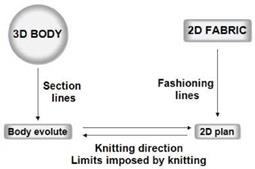
Fig. 15 illustrates the correlation between the 3D shape of the product and the 2D plan of the fabric, emphasising the most significant elements for the knitting process design. The evolute of the 3D body is obtained using sectioning lines and is the same with the 2D plan of the fabric that contains the fashioning lines. The knitting direction is very important when designing a
3D fabric. Knitting along the transversal or longitudinal direction of the final shape determines the knitting programme, the plan aspect and furthermore the specific behaviour of the fabric in the product. In some cases, only one knitting direction with regard to the product shape is possible, the other option being technologically not feasible. Other limitations concern the positioning of the fashioning lines within the fabric and their dimensions.
|
Fig. 15. Correlation between the 3D body and the knitted 2D fabric |
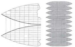
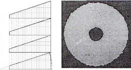
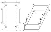
Some of the most representative examples are illustrated in Figs. 16 to 20, presenting the 3D shape and the fabric 2D plan.
|
Fig. 16. (Hemi)spherical shape (Cebulla et al., 2000) |
|
|
|
|
|
|
|
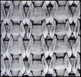
There are some issues related to the fashioned fabrics used as preforms. One is the fabric strength, considering that the weft knitted materials exhibit limited mechanical characteristics. The solution to this problem is to insert warp and weft yarns within the structure. Fig. 21 presents a jersey fabric with warp and weft yarns, produced on a flat machine with adapted yarn feeder for the warp yarns (Cebulla et al., 2000). Apart from giving the fabric strength, it also improves the volume fraction of the reinforcement, increasing the quality of the composite materials.

