 |
|
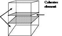
Cohesive elements are used to model the interface between sublaminates. The elements consists of a near zero-thickness volumetric element in which the interpolation shape functions for the top and bottom faces are compatible with the kinematics of the elements that are being connected to it (Davila et al., 2001). Cohesive elements are typically formulated in terms of traction vs. relative displacement relationship. In order to predict the initiation and growth of delamination, an 8-node cohesive element shown in figure 1 is developed to overcome the numerical instabilities.
 |
Fig. 1. Eight-node cohesive element
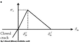
The need for an appropriate constitutive equation in the formulation of the interface element is fundamental for an accurate simulation of the interlaminar cracking process. A constitutive equation is used to relate the traction to the relative displacement at the
interface. The bilinear model, as shown in figure 2, is the simplest model to be used among many strain softening models. Moreover, it has been successfully used by several authors in implicit analyses (De Moura et al., 2000; Camanho et al., 2003; Pinho et al., 2004; Pinho et al., 2006).
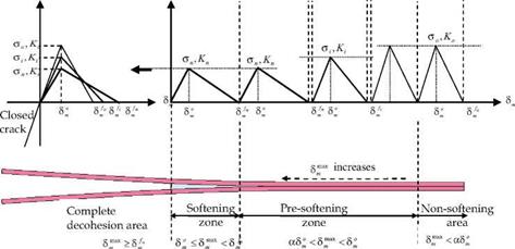
However, using the bilinear model leads to numerical instabilities in an explicit implementation. To overcome this numerical instability, a new adaptive model is proposed by Hu et al. (Hu et al., 2008) and presented in this Chapter as shown in figure 3. The adaptive interfacial constitutive response shown in figure 3 is implemented as follows:
|
о
Fig. 3. Adaptive constitutive model for Mode-I (Hu et. al, 2008) |
In pre-softening zone, aS, < S^3* < S, , the constitutive equation is given by
K = (K +nSm S (1)
Sm
and
Km = KSm (2)
where к is the traction, . K. is the penalty stiffness and can be written as
|
K |
О VI |
|
|
K |
ST <Sm |
(3) |
|
Kn |
Sm S <Sfm |
go = ao _ aj _ a,„
![]() m K~ K ~ K_
m K~ K ~ K_
where ao is the initial interface strength, a is the updated interface strength in the presoftening zone, amin is the minimum limit of the interface strength, Ko is the initial stiffness, Kj is the updated stiffness in the pre-softening zone, and Kmin is the minimum value of the stiffness. For each increment and for time t+1, Sm is updated as follows:
€1 _ +1 – tc (5)
where tc is the thickness of the cohesive element and e‘+1 is the normal strain of the cohesive element for time t+1, єt+1 _ є* + Ає, where As is the normal strain increment. The (S™3*)* is the max relative displacement of the cohesive element occurs in the deformation history. For each increment and for time t+1, АГ* is updated as follows:
|
( omax t +1 c*t +1 (Sm ) _ Sm |
if A+1 > (ST)* and, |
(6) |
|
(gmax)t+1 ___ (gmax)t |
if s, m+1 < (s*)* |
(7) |
Using the max value of the relative displacement АГ* rather than the current value Sm prevents healing of the interface. The updated stiffness and interface strength are determined in the following forms:
It should be noted that a in equations (8) and (9) is a parameter to define the size of presoftening zone. When a =1, the present adaptive cohesive mode degenerates into the traditional cohesive model. In these computations, a was set to zero. From our numerical experiences, the size of pre-softening zone has some influences on the initial stiffness of loading-displacement curves, but not so significant. The reason is that for the region far always from the crack tip, the interface decrease or update according to equations (8) and (9) is not obvious since S™ is very small. The energy release rate for Mode-I GIC also remains constant. Therefore, the final displacements associated to the complete decohesion SMm are adjusted as shown in figure 3 as
St=^C (10)
a
Once the max relative displacement of an element located at the crack front satisfies the following conditions; S™ > Sm , this element enters into the real softening process. Where, as shown in figure 3, the real softening process denotes a stiffness decreasing process caused by accumulated damages. Then, the current strength an and stiffness Kn, which are almost equal to amin and Kmin, respectively, will be used in the softening zone.
2. In softening zone, S°m < Sm* < Sjn, the constitutive equation is given by
![]() 7 =(1 – d)(am +nm S
7 =(1 – d)(am +nm S
Sm
where d is the damage variable and can be defined as
The above adaptive cohesive mode is of the engineering meaning when using coarse meshes for complex composite structures, which is, in fact, an ‘artificial’ means for achieving the stable numerical simulation process. A reasonable explanation is that all numerical techniques are artificial, whose accuracy strongly depends on their mesh sizes, especially at the front of crack tip. To remove the factitious errors in the simulation results caused by the coarse mesh sizes in the numerical techniques, some material properties are artificially adjusted in order to partially alleviate or remove the numerical errors. Otherwise, very fine meshes need to be used, which may be computationally impractical for very complex problems from the capabilities of most current computers. Of course, the modified material parameters should be those which do not have the dominant influences on the physical phenomena. For example, the interface strength usually controls the initiation of interface cracks. However, it is not crucial for determining the crack propagation process and final crack size from the viewpoint of fracture mechanics. Moreover, there has been almost no clear rule to exactly determine the interface stiffness, which is a parameter determined with a high degree of freedom in practical cases. Therefore, the effect of the modifications of interface strength and stiffness can be very small since the practically used onset displacement Sm for delamination initiation is remained constant in our model. For the parameters, which dominate the fracture phenomena, should be unchanged. For instance, in our model, the fracture toughness dominating the behaviors of interface damages is kept constant.


