An analytical formulation for modelling the behaviour of the FRP-to-concrete adhesive interfaces is presented and discussed in the present section. The behaviour of FRP-to – concrete joints in the linear range is examined in the first subsection. Then, the aspects more directly related at the ultimate behaviour are addressed in the second one.
1.1 A general analytical model: formulation in the linear range
A simplified model is formulated in the present section with the aim of simulating the behaviour of FRP laminates bonded on concrete and tested in pull-out, simulating how both the in-plane (namely, "slip") and out-of-plane displacement components develop throughout the FRP length. It is based on the following assumptions:
– the FRP strip is simulated as a Bernoulli beam;
– the adhesive layer is modelled as a bi-dimensional elastic domain in plane deformations.
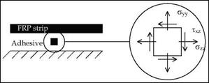
The generalized forces N, V, M applied on the transverse section of the strip at the abscissa z and the interface stresses (shear т and normal a, respectively) are represented in Fig. 2. The following equilibrium equations can be stated between those force and stress components:
![]() dM + Tff – v = 0
dM + Tff – v = 0
 |
dz f 2
Fig. 2. Forces on the segmental FRP strip element
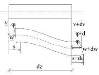
The parameters v, w and ф completely describe the displacement field of the strip and the following compatibility equations relate them to the axial strain є and the curvature X (Fig. 3):
![]()
|
|
|
|
|
|
![]()
|
|||
|
|||
|
|||
|
|
||
|
|||
|
|||
|
|||
|
|||
|
![]()
The corresponding strain measures can be expressed as functions of the displacement field va(ya, za) e wa(ya, za) within the adhesive layer:
![]() _dVa dy a dwa_
_dVa dy a dwa_
dza
where ya and za are the Cartesian coordinates of the infinitesimal areal element of resin. Finally, the following elastic relationships can be stated between stresses and strains:
8yy = ET yy -Va ‘CTzz ]
‘ 8zz = ET ‘l>zz Va -°yy ] , (12)
Y yz =G = 2-(1 +Va )-E-
where Ea and Ga are the elastic properties of the adhesive layer. In this formulation, it connects the FRP laminates to a stiff substrate representing the concrete element. The upper bound of this layer is connected to that strip and some compatibility equations should be written for introducing this physical constraint into the mathematical model. Thus, the three equations (10)-(12) can be worked out for deriving a relationship between the displacement components va(0,za) and wa(0,za) and the corresponding stress components ayy(0,za) and Txy(0,za). A key assumption can be introduced for simplifying the analytical expressions of the interface stresses, considering a constant value of the shear stress throughout the adhesive thickness (Rabinovich & Frostig, 2000):
Tyz =Ta(za) =Ta(z). (13)
Consequently, the second one of the two equations in (10) leads to the following simplification in terms of the normal stress in longitudinal direction:
^ = 0 ^^zz =f1 (ya =0 . (14)
The last implication derives by the assumption of zero axial stress on the initial section of the layer adhesive.
Further simplifications can be introduced looking after the first equations in (10) and introducing therein the stress-strain relationship and the compatibility equation within the adhesive layer:
|
|
 |
|
|
|
|
|
|
|
|
|
|
|
|
|
|
|
|
|
|
|
|
|
|
|
|
|
|
|
|
|
|
|
|
|
|
|
|
|
|
|
|
![]()
|
|
||
|
|||
|
|||
 |
|||
and the corresponding function wa can be derived by integrating eq. (25) and introducing a zero-displacement condition for ya=ta (namely, at the bottom of the adhesive layer):
The above relationship can be utilized for deriving the expression of the axial displacements beneath the laminate (ya=0), corresponding to the slip at the interface s(z):

![]()
![]() (27)
(27)
as well as equation (22) can be utilized for recognizing that the corresponding transverse component va(0,za=z) is equal to v(z):
Thus, the rotation field 9(z) of the laminate element can be easily defined through equation (6) and the generalized strain fields can be determined by means of equation (4) and (5).
The above equations can be finally combined for deriving a unique differential equation in terms of interface shear stresses. A first equation can be obtained by differentiating eq. (7) and introducing (4), (6) and (8). After a further differentiation and introducing the definition of interface slip provided by eq. (27), the following differential relationship between the shear stress and the transverse displacements can be obtained:
Another relationship is obtained by differentiating equation (3) and introducing equation (2), (5), (6) and (9) for expressing both the bending moment and the shear force in terms of transverse displacements and interface (shear and normal) stresses. The final expression of an equation in terms of tf and v (and their derivatives) can be obtained introducing equation (29):
![]() bf (tf + ta ) . djL – Efbftf3 . dv – Eabf. v = 0 2 dz 12 dz4 ta
bf (tf + ta ) . djL – Efbftf3 . dv – Eabf. v = 0 2 dz 12 dz4 ta
|
Ga |
• T – d2 Ta +f ta2 + tatf + tf2 Ї |
Ga |
d4Ta |
E t t 3 n fLaLf |
d6T EfG t 3tf3 a | f a a f |
d8T •di = 0. (32) dz |
|
Eftfta |
a dz2 ^ 3 6 12 J |
Ea |
dz4 |
12 • Ea |
dz6 144 • Ea2 |
Finally, an expression of the displacement function v as a function of the interface shear stresses can be derived by solving equation (31) and introducing the (30):
Eight boundary conditions are needed for the problem at hand and they can be symbolically written as follows:
|
Ta|z=0 = 0 , Ta|z=L = 0 , |
(34) |
|
N(0) , N(L) |
(35) |
|
0 EfAf ‘ lz=L EfAf ‘ |
|
|
О II hJ Y О II о Y |
(36) |
|
_< II О _< II О |
(37) |
 |
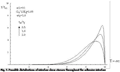
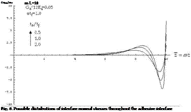
Typical solutions of the problem described by equation (32) and the boundary conditions (34)-(37) are represented in figures 5 and 6, in terms of shear and normal stresses respectively. In both graphs, the interface stress components are divided by the average shear stress Tm=F/bfL and the abscissa are reported in non-dimensional form as z = rnz.
The results of the analysis carried out by means of this model are completely controlled by the following non-dimensional parameters:
|
In t k t. |
|
|
Eft a Ea ‘ |
(39) |
|
G k |
|
|
Ea kv, a ‘ |
(40) |
|
ta tf ‘ |
(41) |


