Some of the principal anatomical and anthropometric aspects will be considered. For detailed specifications, some excellent handbooks are to be recommended (for example, Morgan et al., 1963; Grandjean, 1988). One important limitation of the recommendations available today is that they are based on the body measurements of Caucasians. For other ethnic groups, the measurements must be adapted for their proportionally shorter or longer leg lengths.
The following rules can be applied in the design of all types of control:
1. The maximum strength, speed, precision, or body movement required to operate a control must not exceed the ability of any possible operator.
2. The number of controls must be kept to a minimum.
3. Control movements which are natural for the operator are the best and the least tiring.
4. Control movements must be as short as possible, while still maintaining the requirement for ‘feel’.
5. The controls must have enough resistance to prevent their activation by mistake. For controls that are only used occasionally and for short periods, the resistance should be about half the maximum strength of the operator. Controls that are used for longer periods must have a much lower resistance.
6. The control must be designed to cope with misuse. In panic or emergency situations, very great forces are often applied, and the control must be able to withstand these.
7. The control must give feedback so that the operator knows when it has been activated, even when this has been done by mistake.
8. The control must be designed so that the hand/foot does not slide off or lose its grip.
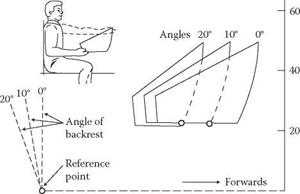
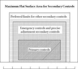
Table 5.1 gives a summary of the areas of use and the design recommendations for different controls. The controls are discussed in more detail later. Figure 5.1a, Figure 5.1b, and Figure 5.1c give the optimal areas for the different controls.
Stepwise Adjustments Continuous Adjustments
|
Rotary Switch |
Hand Push-Button |
Foot Press-Button |
Toggle Switch |
Small Wheel |
Wheel |
Crank |
Pedal |
Lever |
|
|
Large forces can be developed |
— |
— |
— |
— |
No |
Yes |
No |
Yes |
Yes |
|
Time constraint for adjustment |
Medium |
Fast |
Fast |
Very fast |
— |
— |
— |
— |
— |
|
Recommended number of |
3-24 |
2 |
2 |
2-3 |
— |
— |
— |
— |
— |
|
positions |
|||||||||
|
Space requirements for placing and using |
Medium |
Small |
Large |
Small |
Small to medium |
Large |
Medium to large |
Large |
Medium to large |
|
Activation by accident |
Small |
Medium |
Large |
Medium |
Medium |
Large |
Medium |
Medium |
Large |
|
Limits of control movements3 |
270° |
3.2 x 38 mm |
12.7×100 mm |
120° |
None |
±60° |
None |
Small3 |
±45° |
|
Legibility |
Good |
Acceptable |
Bad |
Acceptable |
Badd |
Acceptable |
Acceptable |
Bad |
Good |
|
Visual identification of control position |
Acceptable |
Badb |
Bad |
Acceptable |
Acceptable0 |
Bad to acceptable |
Bad |
Bad |
Good |
|
Checking control position on |
Good |
Badb |
Bad |
Good |
Good |
Bad |
Bad |
Bad |
Good |
|
panel together |
|||||||||
|
Usability as part of a combination |
— |
Good |
Bad |
Good |
Good |
Good |
Bad |
Bad |
Good |
|
of controls |
|
TABLE 5.1 Recommendations for Controls |
a The exception is “cycle ” pedals, which have no limit.
 b The exception is when the control is back-lit and the light goes off when the control is activated. c Only usable when control cannot be turned more than one revolution. Round wheels/knobs must be marked. d Assuming that control can be rotated more than one turn.
Reference point is at the angle between seat and backrest
 |
I_____ I_____ I_____ I_____ I_____ I_____ I_____ L
![]()
![]() 0 10 20 30 40 50 60 70
0 10 20 30 40 50 60 70
Forward from Reference Point, cm
(a)
|
-20 -15 -10 -5 0 5 10 15 20 Distance to the Right and Left of Seat Reference Point, cm (b) |
FIGURE 5.1 (a and b) Preferred vertical surface areas and limits for different classes of manual controls. (Modified from McCormick and Sanders, 1982. With permission.)


