The terms to be used in this section are defined as follows:
Scales range—The numerical difference between the lowest and the highest value on the scale.
Numbering interval—The numerical difference between two successive numbers on the scale.
Scale marking interval—The numerical difference between two scale markings.
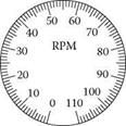
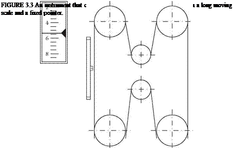
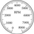
Before choosing a scale for an instrument, one must determine the precision required. Figure 3.5 gives examples of different precisions. It is generally true that the least exact scale that fulfils system requirements should be chosen, thus avoiding unnecessary accuracy. If possible, the information should be given in units that require no modification by the operator before they can be used. An example of this might be percentage figures being used instead of the actual number of revolutions,
 |
so that the operator need not remember different top speeds on different machines (a scale speed is often the same percentage of top speed on all machines). The percentage scale also gives fewer digits to read off (see Figure 3.6).
Figure 3.7 shows examples of recommended scale designs for instruments with different scale ranges. On the horizontal axis are the marking intervals, 1, 2, 5 (and 1/10 and 10 times these values). This means that for 2 there are two (or 0.2 or 20) units between each subsidiary marking. On the vertical axis are the numbering intervals, that is, the numerical difference between two successive numbers on the scale.
The matrix in Figure 3.7 shows examples of recommended scales and examples of how the markings can be designed. The scale can either be marked with large, medium, or small sizes of marks. Certain of the scales use all three sizes. Large markings are always used for the numbers of the scale. Medium-sized and small markings are used for subdivisions, that is, those divisions which lie between the numbered markings.
There must not be more than nine subdivisions between numerical markings. The scales should preferably be designed so that interpolation between divisions is not necessary. Where there is a lack of space, however, it is better to allow interpolation than to clutter up the instrument with too many markings. If there is room for the scale illustrated in Figure 3.8a, this is the one to choose; otherwise, choose the one shown in Figure 3.8c. The scale in Figure 3.8b is not suitable. If the alternative in Figure 3.8c is chosen and the scale has to be read off to the nearest whole number, this means having to interpolate one step between markings. The smallest
|
|||||||||||||||||||||||||||||||||||||||||||||||||||||||||||||||||||||||||||||||||||||||||||||||||||||||||||||||||||||||||||||||||||||||||||||||||||||||||||||||||||||||
|
|||||||||||||||||||||||||||||||||||||||||||||||||||||||||||||||||||||||||||||||||||||||||||||||||||||||||||||||||||||||||||||||||||||||||||||||||||||||||||||||||||||||
|
|
|
|
|
step for which it is necessary to interpolate is called the subjective scale division. There should be zero, two, or five subjective scale divisions for every marked interval. The basic factor in the reliability of reading an instrument dial is the physical width (measured as an angle of view) of subjective scale divisions (that is, zero, two, or five subjective scale divisions per marked interval). The scale is subdivided in such a way that the reading tolerance and accuracy one wishes the instrument to have are achieved. Accuracy must not be greater or even less than the allowable pointer error for the instrument in question. If it is necessary to interpolate fifths in order for the correct degree of accuracy to be obtained, the angle of view must be five times the angle of the subjective scale division, which equals the smallest division for which it is necessary to interpolate. If the viewing angle for the subjective scale division is less than a certain critical size, there will be considerable errors in
 |
FIGURE 3.7 Examples on recommended scale division for different sizes of the scale.
0 10 20 30 40 50
1 I I I I I I I I I I I I I I I I I I I I I I I I I I I I I I I I I I I I I I I I I I I I I I I I I I
(a)
0 10 20 30 40 50
IiiiiIiiiiIiiiiIiiiiIiiiiIiiiiIiiiiIiiiiIiiiiIiiiiI
(b)
0 10 20 30 40 50
1 I I I I I I I I I I I I I I I I I I I I I I I I I
(c)
FIGURE 3.8 The physical size of the scale and the number of scale divisions. Scale (b) is not to be recommended.
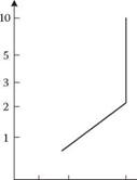
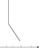
reading it. If, on the other hand, the angle of view of a subjective scale division is greater than this critical size, one cannot expect any further increase in reliability of reading, as shown in Figure 3.9, according to which the width of the critical scale division is 2 minutes of arc.
The reading reliability over this critical value would be expected to rise to 99% for people with long experience of instrument reading. When designing a scale, therefore, one would start by determining the greatest distance at which the scale is going to have to be read. Based on the distance and the critical angle of 2 minutes of arc, the smallest size of the subjective scale divisions which will be needed on a scale is calculated from the total measuring range the instrument is to have. Knowing that
 |
20 40 60 100 1 2 3 4
 |
% Correctly Read Time (s)
(reading accuracy)
FIGURE 3.9 Effect of subjective scale division on reading accuracy and time. Increasing the subjective scale division to greater than 2 minutes of arc does not increase the reading accuracy or reduce the reading time. (Murrell, 1958. With permission.) there should be two or five subjective scale divisions between each marked interval, the number of marked intervals can be selected. There should be two, four, or five marked intervals for each numbered interval.
For a scale marked in five subjective scale divisions per marked interval, and which has a total of 100 subjective scale intervals, the total length of the scale is determined according to the reading distance obtained from the following formula:
D = 14.4 L (3.1)
D is the reading distance and L is the length of the scale. D and L have the same units of length, for example, cm. If one does not have such a ‘standard scale’ with the above relationship between subjective scale division and marking interval, there is a correction factor that may be added to the formula:
14 4 x L = [D x (i x n)] / 100 (3.2)
where i is the number of subjective scale divisions into which each marking interval is to be interpolated, and n is the number of marking intervals. In practice one is often tied to existing standard instruments. Here one can instead evaluate the maximum reading distance for the different instruments and determine whether this is sufficiently far for the actual application.
The scale itself should not have long lines joining up the scale markings, but should be open (see Figure 3.10). Figure 3.11 gives the recommended measurements of the scale marking for (a) normal visual conditions, and (b) low light levels. In this case, the reading distance is approximately 70 cm. The measurements given in
Unsuitable scale with connecting lines
Suitable scale without connecting lines
FIGURE 3.10 Examples of suitable scale designs.
FIGURE 3.11 Recommended design of scales (mm).
Figure 3.11 apply not only to straight instruments but also to circular and segmentshaped ones.
The design of the letters and numbers on the scale is important for giving the best possible reading reliability. The following points should be noted especially:
1. The ratio between the thickness of the line and the height of the letter/ number for white numbers on a black background should be between 1:10 and 1:20. If the background is dark and the numbers are illuminated from behind, the optimum is between 1:10 and 1:40. The optimum for black letters on a white background lies between 1:6 and 1:8. Black lettering on a white background is normally preferable. For dark-adapted and low-illumination conditions, white numbers on a black background are preferable (for night viewing in combination with red instrument lighting, the white numbers will be seen as red).
2. The ratio between the height of the numbers/letters and their width should lie between 2:1 and 0.7:1. The optimum is 1.25:1.
3. The appearance of the numbers/letters is important. As a guide, the num – bers/letters should be simple in their design. Serifs and too many lines complicate the reading. However, they must not be so simple as to become difficult to understand.
4. Letters/numbers must not be positioned on the scale in such a way that they are shaded by the pointer, and they must be vertical.
The following recommendations are made on the design of the pointer:
1. The pointer must be long enough to reach but not to overlap the scale markings.
2. The pointer should lie as close to the surface of the dial as possible in order to avoid parallax errors.
3. The section of the pointer that goes from the pivot to the scale markings should be of the same colour as the scale markings. The remaining part of the pointer should be of the same colour as the dial face.
4. On horizontal scales, the pointer should sit on the top of the scale, and for vertical scales it should be on the right-hand side with the numbers on the left.


