Even where the operator usually works alone, it occasionally happens that there are several other operators working in the same control room. And even an operator working alone will have several workplaces at different locations within this control room. It is important that the different workplaces are positioned in the correct relationship with one another. For the work to be done efficiently, the operators must be able to have contact with one another easily without needing to be disturbed. Teamwork should also be encouraged by the appropriate positioning of workplaces.
In order to fulfil these various aims in the siting of different workplaces in a control room, frequency and sequence analyses may be used. The best positioning of machines, instruments, and operators in relationship to each other is achieved if the various forms of connections (such as movements and messages), which are important for the system under design, are optimised. The term connection here means all
forms of contact among operators and between operators and machines. Examples of this are that the operators need to be able to talk to each another, and they must be able to read particular instruments in order to carry out particular control movements. Connections also include moving between two places or moving material from one place to another.
Optimisation of the connections means that necessary contact is easy to ‘service’, which normally implies that a person with whom one has frequent contact sits close by, and someone contacted only occasionally sits farther away. Also, instruments that are used regularly should be positioned close to the operator, while less frequently-used instruments should be positioned farther away. In addition, the contacts that are important—for example, those that reduce the risk of serious faults—should be well positioned in relation to the appropriate operators and instruments.
Whether the contact for a certain connection is good or not depends to a large extent on the type of contact. If the task is one of supervision (for example, to see what another operator is doing, because their information is required for one’s own work), one can sit behind, at an angle behind, or slightly above the other worker. If it is more a question of talking to each other and having a mutual interchange of information, it is best to sit opposite, or almost opposite, one another.
A link analysis is done in the following way:
1. Draw a circle for every person included in the system, and write down their function (e. g., supervisor or operator).
2. Draw a square for each part of the machine used by the operator and indicate its functions using letters or symbols.
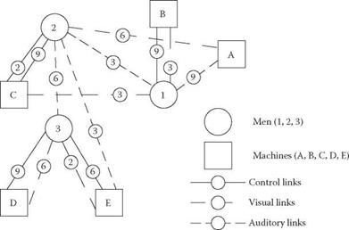
It is of no great importance how the circles and squares are positioned at this stage, as long as they are distinguishable (see Figure 6.1a).
3. Draw lines between the operators who have connections with each other in the system.
4. Draw lines between each operator and the machines he or she will have contact with.
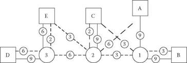
5. Redraw the diagram so that the lines cross each other as little as possible (see Figure 6.1b).
For many analyses, this procedure is sufficient. It shows how the operators and machines interact, and how they can be separated where there is no contact between them and brought together where closer contact is required. Where many of the paths cross, the frequency and importance of use must be examined. This is achieved by comparing every connection using at least one of the following methods:
1. Where importance is the criterion, an experienced person who knows the different parts of the system can be used to rank all the links in order of their importance.
2. Where frequency is the criterion, information from a simulation of the system can be used in order to determine the relative frequency of the contacts, and then to rank the transactions accordingly.
|
(a) Original arrangement |
|
(b) Rearrangement FIGURE 6.1 Example of the positioning of operators and machines based on the contact between them (the frequency of contacts is indicated by the figures in the smaller circles). |
3. In cases where both frequency and importance are the criteria, the experienced operator can again be used to assess the various links and to rank – order them.
An excellent way of making a diagram of this type clearer is to draw thicker lines to indicate the most frequently-used or important links.
1. Redraw the diagram so that the links that are the most important/most frequently used are the shortest, and reduce the numbers of crossings. This is now the optimal link diagram.
2. Redraw the diagram again so that it fits into the proposed space, or even better, redesign the space so that it fits the diagram.
3. Determine the final diagram on a scaled drawing using the actual positioning of the operators, machines, and equipment in the system. A drawing of
this type helps in the visualisation of the physical space required. It may also be a help in detecting difficulties that were not discovered in the analysis.


