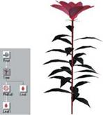
Although the rendering of trees requires a relatively small number of components, experience with the system is necessary. Thus, we suggest to first model a small flower. The final result was used for the interactive rendering of plants and can be seen in Fig. A.3. The description given here refers to the Xfrog Version 3.5, for the Version 4.0, which is integrated in Cinema4D, slightly different components are used.
 Figure A.3
Final desired result for the plant modeling
After starting the program, a leaf component from the area at the lower left in the modeling environment is selected by double clicking. After it appears in the structure editor, it will be connected with the camera. The description for the structure and the view of the geometry are seen in Fig. A.4.
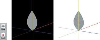 Figure A.4
(a) Initial structure; (b) geometry with black and (c) white background
For the following screenshots of the system, the background color (above the geometry dialog window) was set to white, and a wireframe rendition was chosen (menu “Shading”) for the triangle edges. The world coordinate system was also removed (menu “Display”). This then correlates with the appearance of the example that is shown further down.
The leaf should be textured in order to give it a realistic look. For doing so, the leaf component is clicked, and in the displayed parameter editor the subitem “Material” is selected. The texture menu appears. Now the provided texture with the name “impatiens_newguinea_hybris_petal. png” is selected. See the dialog and the strange-looking geometry in Fig. A.5.
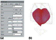 Figure A.5 (a) Material editor of the leaf component; (b) geometry, distorted by initial leaf component parametrization
The shape evolves from the initial shape of the leaf; the system was preset to display a leaf shape without texture. Thus, in the parameter editor under “Leaf” the parameter “Shape” is set from “Range” to “Spline”, and “Edit” is selected. in the appearing editor, all points except for the uppermost one, are dragged onto the edge, so that an square-like shape is created (see Fig. A.6).
Figure A.6
(a) Form editor of the leaf component;
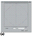
 (b) after setting
Now the texture only has to be moved on the lower side of the leaf geometry. For this, you have to return to the material editor. The move takes place through the changing of the U – and V-coordinates, which describe the positioning of the texture at the corner points of the leaf geometry. At the sub item “shift V”, you can set the possible minimal and maximal values of the control to -1 and 1 before changing the value in order to increase the accuracy of the control. Here you simply click on these values and enter the new value. of course, you can also directly enter the value, as shown in Fig. A.7a; simply click on the number field. To stretch the texture, increase the “Scale V” to a value of eight.
Figure A.7

![]()
 (a) Material editor of the leaf component; (b) geometry after adjusting the texture
(a)

 |
For modeling the flower, the leaf is to be multiplied through a phiball component. The component is selected and linked to the camera, then the leaf component is linked to the phiball. As a default, 50 leaves are created, which, according to the Golden Section, are arranged on a sphere. By changing the number to five, reducing the radius to zero, and changing the spherical section (“Fan”) to the values of 0 and 0.3, we already get closer to completion of the flower. The leaves are now intersecting each other and must be arranged in a correct way. Here we click on the leaf component, and under the section “Leaf”, the initial value of the “Rotation X” is set to two (see Fig. A.8c).

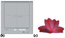
 |
The operation causes a bending of the leaf along the main axis. The curvature perpendicular to the main axis is set at another place, since it relates directly to the rendered geometry primitives (in this case the triangulated point list). For doing so, in the “Primitive” editor, the entry “Profile” is set to “On”, and in the respective editor the shape is set according to Fig. A.9.
In the next step we will create the normal leaves. To do this, the part of the plant defined so far is dragged away from the camera component, and a new leaf component is defined. Onto this, analogous to the above, the texture “im-
patiem_newguinea_hybris_leaf. png” is applied, and appropriately scaled. The components and the leaf geometry are shown in Fig. A.10.
Figure A.10
(a) Components after defining the leaf;
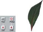 (b) leaf geometry
(a) (b)
The leaf geometry is linked to a tree component, which in turn is linked to the camera component. At first look, the result is not very promising (Fig. A.11), since there are still some parameters to be changed. if the leaves should be smaller than in the image, the scaling on the primitive parameters of the leaf component can be changed. But let us return to the tree component. The diameter can be decreased using the “Shape” parameter. Now we apply the texture with the somewhat long name “impatiens_newguinea_hybris_bark. png” onto the tree geometry, and in the menu “Tree” the number of leaves is increased to 24 (see Fig. A.11c).
|
|
|
|
|
|
|
|
|
|

![]()
In the next step the flower must be attached to the tree component. For this, the partial description of the blossom, which was laid aside, must be dragged onto the tree component. The link type for the connection between the tree and the phiball component now has to be set from “multiple” to “simple”, i. e., the link itself has to be clicked and must be adjusted by the link type editor below the window. Finally, the scaling of the phiball component (in “Basic Parameters”) is used to set the size of the flower. If the diameter of the tree component is changed accordingly, we have created a nice-looking branch. The still bothering jags in Fig. A.11e, shown below the flower, are removed using the leaf component in the part “Primitive” by adjusting the “Separator On”. This prevents the triangulation of both geometries by the system.
 |
 |
 |
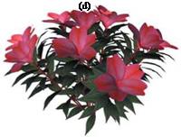 |
Now the branching characteristic of the tree component must be changed, so that there will be more leaves at the top than at the lower part. The “Distribution” parameter in the tree component (“Tree”) is responsible for this. It will be changed so that, when moving to the upper part, the values increase (Fig. A.12a). There also the angles of the leaves are adjusted using the “Angle” parameter.
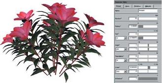
In the next step, these branches are to be connected to the plant. In addition, a phiball component is selected, and before it is linked to the camera the number of multiplications is set to 10. Additionally, the opening angle is reduced, as we did with the flower. Now the remainder of the structure can be linked to this component, and all components are linked to the camera. In Fig. A.12d we see the result, which, however, still has to be refined a little.
For doing so, the radius of the ball is increased in the phiball component the branches are attached to. Also, using the “Scale”-parameter an individual size can be given to each branch. These sizes have to be adjusted in such a way that the outside branches are somewhat smaller than those on the inside. In Fig. A.13 an exemplary adjustment of the parameters and the result can be seen. For the last step we return to the tree component. The branches should bend somewhat upward, toward the light. Such curvatures are implemented using tropisms. To do so, adjust the phototropism value of the tree component at the right end, this will bend the upper parts of the branches toward the light. You
 |
should receive a result as shown in Fig. A.14. If you want to achieve a still result more similarly to that in the first figure, then increase the number of branches and vary the “Scale”-parameter in the phiball component.
in order to produce a high-quality image from the geometry, you must transfer the data to a rendering system. This can be done either by selecting a format in the menu “Export”, and thereby storing the data, or by using one of the Xfrog plugins, to transfer the data into a rendering system such as 3D StudioMax or cinema 4D directly. Different plugins are available on the Greenworks website (www. greenworks. de). Beyond that, diverse plants have already been premodeled, so that you can assemble more complex scenes. Doing so, we almost touch the borders of interactive computer graphics, if the LOD models already mentioned are not used. To implement a complex scene in the Xfrog modeling system, and to also adopt it to a rendering system will unfortunately only be possible in the future, at least for larger numbers of plants.

