The web site to this book, found at “www. computerpflanzen. de” contains useful information, links to a collection of programs, and data and video sequences. Most of the content is related to our modeling system “Xfrog” which also can be downloaded there in a demo version usable with full functionality for 30 days. In the following, a practical introduction to modeling is given, which should help the reader create plants and other objects by him-/herself.
A.1 The Xfrog Modeling Environment
 |
The basis of the program was designed in 1998 by the authors. During the years following, in cooperation with different coworkers and with generous support from the Intel Corporation and the ZKM Center for Media Arts and Technology, Karlsruhe, the program was further developed.
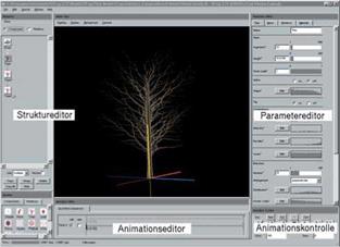
The program is an integrated modeling environment consisting of several dialogs (see Fig. A.1). In the structure editor the user constructs the structural
description of the plant. The individual parts of the plant are generated with the components that were already introduced in Chap. 6. These components are activated in the field at the lower left through double clicking or by dragging them into the structure editor.
 connecting a component with the camera results in the creation of a geometry (if the component produces any), which is indicated in the large middle dialog window. In this dialog window, the 3D geometry can then be moved with the mouse, turned and scaled. The right, the left, and both mouse buttons are used, respectively, for these operations.
If a component is double clicked with the mouse button, the corresponding parameter editor appears on the right side of the dialog window. With this editor the individual parameters of the component can be changed. As already described, a basic parameter set exists for all components, as well as a number of individual parameters.
|
|
||||||||||||||||||||||||||||||||||||||||||||||||||||||||||||||||||||||||||||||||||||||||||||||||||||
(a) (b) (c)
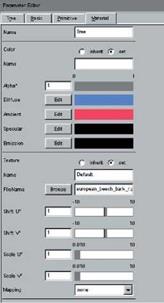
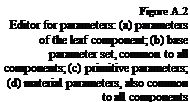
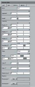
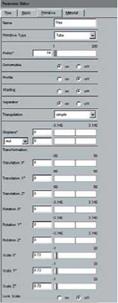
Figure A.2 shows an example of a parameter editor. If the outer left marker of the four markers on the upper side is selected, the individual parameters of the component, here a leaf component in part (a), appears. In the second part, the base parameter as well as the scaling or rotation can be influenced. The third marker (part (c)) includes the primitive parameter, which appears when the component generates a geometric primitive. This is not activated for all components; however, if necessary, it can always be set by the user. In this context, also the material parameters (part (d)) are of importance, since they determine the appearance of the primitives, if the material parameters are not inherited by the components above in the structure.
The last two dialogues of the program are used for animation. As already mentioned at the end of Chap. 6, in Xfrog a parameter-based keyframing is used. Here, at several time steps, the model is given an individual appearance by the user through modification of the parameters, which are then interpolated for the intermediate times by the system. In the animation editor, these keyframes can be created, while the playback of the animation is controlled using the animation control function.

