1.1 General presentation
Fatigue tests on plastics and composite materials must be performed under similar conditions to those operational (frequency, environmental conditions, specimen geometry, etc.). Materials testing machine for dynamic load in alternate plane bending is constituted by three modules:
1. the first module (or control module) generates a sinusoidal movement;
2. the second module can modify loading conditions;
3. the third module (or module data acquisition) measures the stress (load) and analyzes the values through the computer to plot the curves of the load versus the number of cycles.
1.2 The first module (or control module)
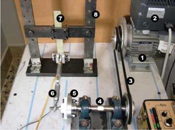
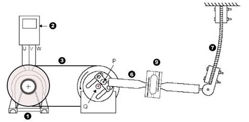
Figure 1 shows the built and used structure to perform fatigue tests in plane bending. A three-phase electric motor (1) with inverter (2) (to adjust the frequency of loading from 0.04 to 23 Hz) rotates a pulley (with throat z) that, via a link belt (3), places in rotation an intermediate shaft (4) with transmission ratio equal to one. The transmission ratio is verified by optical tachometer, monitoring the number of rotations of the crankshaft and the corresponding speed of the drive shaft. Power transmission by belt ensures the electrical insulation of the specimen by the engine, with particular advantage if the specimens contain metal or carbon. An eccentric cam system (5) allows to transform the circular motion in a purely symmetric and oscillating motion of the solicitation rod (6). The specimen to be tested (7) is stuck to a rigid frame at one end (8) and stressed by the rod load at other end.
|
Fig. 1. Materials testing machine |
Stress magnitude is determined by the distance between the points P (mobile) and Q (fixed) (Figure 2). It is possible to change load type (alternate or pulsatory) depending on the eccentricity and variable length of the connecting rod. The development of load-number of cycles is monitored at regular intervals or continuously, for all imposed displacement.
|
Fig. 2. Schematic representation of materials testing machine |
|
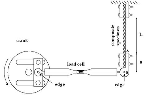
Fig. 3. Schematic representation of the second module |
1.3 The second module
The second module (Fig. 3) allows to vary the length of the connecting rod and to modify some geometric values. The extension of the rod can be varied in a micrometer way in order to adjust the scale of imposed displacement and consequently the type of stress (alternate, symmetric or throbbing). In this way the deflection of the specimen can vary from zero up to a maximum value, quite apart from the load type. Moving the crossbar panel, tests on specimens of different lengths can be performed, with the maximum force depending on the power of the engine installed.


