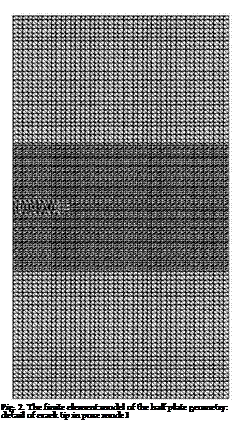
A finite element analysis of the configuration in Fig.1 is carried out, using the finite element code Franc2D/L developed at Kansas University (Swenson & James, 1998).
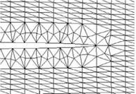
The plate, without patch, was meshed using standard six node-isoparametric elements with triangular shape, as showed in Fig.2. These elements perform well for elastic analysis and have the advantage that the stress singularity at the crack tip can be incorporated in the solution adopting the quarter-point location method (Henshel & Shaw, 1975). The strain energy release rate is calculated using the modified crack closure method and then the stress intensity factor from the Eq. (5). The values are reported in the Table 5.
 |
 |
For the loading condition #3 the value of Kf is close to the fracture toughness. The numerical values are in good agreement with the analytical ones but they are always higher. Fig. 3 presents the comparison between analytical and numerical evaluation of the stress intensity factor as function of the crack length.
The Fig. 3 shows that the good agreement between analytical and numerical results does not depend on the crack length.
|
Analytical |
Numerical (FEM) |
Difference [%] |
|
|
Strain Energy Release Rate: Gi [MPa m] |
|||
|
Test 1 |
2.919 ТО-3 |
3.030 -10-3 |
3.80 |
|
Test 2 |
6.567 ТО-3 |
6.817-10-3 |
3.81 |
|
Test 3 |
1.167 ТО-2 |
1.21210-2 |
3.86 |
|
SIF: Ki*[MPaVm] |
|||
|
Test 1 |
14.23 |
14.45 |
1.54 |
|
Test 2 |
21.61 |
21.68 |
0.32 |
|
Test 3 |
29.37 |
28.91 |
1.57 |
|
Table 5. Analytical and numerical values |


