There is a great variety of fibre-optic measuring methods which are used in the monitoring of composite structures. Therefore in the literature survey the authors decided to focus on the areas in which they have considerable achievements and experience. Among others, the monitoring of laminates and pultruded composites, structural aircraft components, SMART magnetic composites and composite pressure vessels for storing CH2 and CNG is discussed.
1.2 Reinforcing laminates and pultruded composites
Optical fibre sensors have found the widest application in the measurement of deformations of all kinds of laminates and pultruded composites. This is owing to several advantages which OFS have, such as:
– similar material properties of the sensor and the reinforcing material in the composite,
– OFS, even the ones complicated in shape, can be located directly in the material (sensor small size and weight and measuring head flexibility),
– resistance to electromagnetic interference (the sensor is a dielectric),
– a wide range of measured physical quantities and simultaneous measurement in many points,
– resistance to environmental conditions.
 |
 |
OFS, usually in the form of bare-fibre Bragg gratings or interferometric sensors, are located directly between the successive layers of the laminate or are interwoven with reinforcement bundles in the case of woven/drawn elements. Depending on the method of manufacturing the composite and its end use, the sensor may be impregnated with resin during the production of the material ("wet" methods such as pultrusion and winding) or later using the vacuum method.
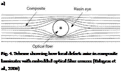
Nevertheless, one should also note potentially negative aspects which need to be taken into account or eliminated (or their effect minimized). One of the drawbacks is the sensor size. Even though the optical fibre diameter is relatively small (typically 125 pm), it is quite considerable in comparison with that of the fibres used to reinforce the composite (amounting to ~16 pm for glass fibres and ~8 pm for carbon fibres) and with the thickness of a single laminate layer. Thus by locating the optical fibre inside the composite one may introduce areas of reinforcement discontinuity (Lee et al., 1995). These areas are excessively filled with resin and are referred to as resin pockets or resin eyes (Fig. 4). The disturbances n stress field distribution in the material may initiate delamination of the latter (Balageas et al., 2006; Udd et al., 2005).
The size and shape of a local defect in the form a resin pocket depend on the orientation of the optical fibre relative to the reinforcement fibres. The laminate’s mechanical parameters are least affected when the sensor is laid along the direction of the reinforcement and most affected when it is laid perpendicularly to the latter. If the sensor is laid parallel to the reinforcing fibres and the two ends of the optical fibre are led outside the area of the sample, the size of the additional defect in the laminate is close to zero (Balageas et al., 2000).
Another aspect which needs to be considered is the effect of the process of manufacture of composite laminate on the measuring properties of the FBG sensors located inside it. In (Kuang et al., 2001) the authors analyzed the spectrum reflected from the fibre Bragg grating in the reference environment (outside the composite before installation), comparing it with the response of a sensor embedded directly between the layers of the laminate. For some test samples they found the spectrum reflected from the sensor to be distorted and widened. This was due to the locally strong nonuniformity of the load acting on the sensor along its whole length (7 mm). Such local nonuniformities in the distribution of the strain field resulted mainly in an increase or decrease of the Bragg grating constant (Л), which manifested itself in the splitting of the single Bragg wave peak into several peaks. This behaviour of the sensor was observed mainly for laminates consisting of several composite layers laid at different angles relative to each other. In the case of unidirectional composites, only a shift of the reflection (Bragg wave) spectrum towards lower values, due to the local
compression or tension of the sensor as a result of the manufacturing process (e. g. resin curing in elevated pressure and temperature conditions), was observed. The possibility of fibre-optic monitoring of resin curing during the manufacture of high-strength laminates was described by, among others, Leng in (Leng & Asundi, 2003). Thanks to the use of FBG and EFPI sensors residual strains during curing can be determined and local material defects in the form of delaminations can be detected. The quoted authors prepared samples made up of 16 layers of carbon prepregs, between which optical fibre sensors were installed along the direction in which the reinforcement had been laid. In addition, a Teflon disk 300 mm in diameter was placed in one of the samples to simulate a local delamination. In order to harden them the samples were annealed at a temperature of up to 120°C. By analyzing the signals received from the sensors installed in the samples with and without the defect one could detect the local damage already during the curing process. It was also found that residual strains after the curing of the samples are greater along the direction of compression for the flawed sample. The difference between the signals received from the EFPI and FBG sensors for the samples during curing amounted to 5-10% (Leng & Asundi, 2003). Then in order to determine their bending strength the samples were subjected to the three-point bending test. The test results confirmed that the strength of the samples with the designed flaw was lower than that of the samples without the flaw and that the artificially introduced delamination reduced the stiffness of the structure (Leng & Asundi, 2003).
One of the main uses of laminates and pultruded composites is the reinforcement of the existing structures or structures under construction. The strength and load-bearing capacity of such structures as bridges, viaducts and buildings are commonly increased by introducing (through bonding) additional reinforcement made of materials characterized by high tensile strength and stiffness (e. g. laminates or pultruded composites in the form of strip or mat) glued to the surface of the structure being reinforced. Thanks to its relatively little weight the reinforcement does not additionally weight down the structure.
But composite reinforcements have drawbacks – they tend to creep and are brittle. For this reason research is underway aimed at the detection and control of internal material defects at the early stage in their development (Majumder et al., 2008). For example, a method of manufacturing glass fibre reinforced composites (GFRC) and carbon fibre reinforced composites (CFRC) through pultrusion with FBG and EFPI sensors located inside is presented in (Kalamkarov et al., 1999). The quasi-static and cyclic test measurement results received from the optical fibre sensors for the tested samples were in agreement with the results obtained from extensometric measurements. Moreover, it was shown that optical fibres with polymer cladding are characterized by better parameters of the sensor/material bond. Sensors in acrylic cladding tended to separate from the laminate and could not be used in composites which required manufacturing processes conducted at a temperature of above 85°C. In the case of the sensors in the polymer cladding the allowable temperatures were as high as 385°C (Kalamkarov et al., 1999).
The use FBG sensors located in pultruded epoxy-glass (GFRP-OFBG) and epoxy-carbon CFRP-OFBG) composites designed for reinforcing concrete beams is described in (Zhou et al., 2003). The composite elements prepared in this way were cast in concrete, cured and subjected to three-point bending. The FBG sensors registered the strains of the composite rods in a range of up to 200 microstrains (with an accuracy of 1+2 pe), registered the cracking of the concrete layer and informed about the slipping out of the reinforcements from the concrete. The authors showed that pultruded composite rods (with incorporated

sensors) can be used both as elements increasing the load-bearing capacity of a structure (reinforcing the latter) and as measuring heads integrated directly with the monitored element.
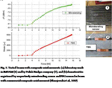
Above one can find exemplary results of investigations into the monitoring of composite reinforcements of engineering structures, carried out by the present authors. Composite reinforcements, in the form of pultruded CFRC and GFRC strips, were glued to the tested concrete beams. Besides the reinforcements, two types of optical fibre sensors, i. e. FBG sensors and amplitude microbending measuring heads, were employed. Figure 5a shows two tested concrete beams with composite reinforcements (made in the laboratory in the Institute of Materials Science and Applied Mechanics (IMSAM) at Wroclaw University of Technology and by the Polish Bridges (PB) company) and embedded optical fibre sensors.
 During three-point bending in an MTS810 strength tester the following were registered as a function of time: the force, the strain (measured by the FBG sensors) and the change in optical power (registered by the microbending head).
a)
 |
b)
local deiamination
Force [kN]
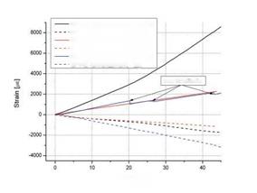
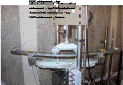
Fig. 6. Four-point bending of steel beam reinforced with unidirectional carbon-epoxy composite with integrated FBG sensors (a) and comparison of measurement results for different reinforcements (b)
Figure 5b shows exemplary measurement results for the microbending sensor and the FBG sensor, as a function of the force applied to the tested concrete beam with the Polish Bridges reinforcements. Similar measurements were carried out for concrete beams without reinforcement and with the laboratory made glass composite and carbon composite reinforcements. On this basis the effect of the type of reinforcement on the strength of the concrete beams was determined. The tests confirmed the suitability of optical fibre sensors for the testing of engineering structures reinforced with elements made of composite materials (Blazejewski et al., 2007).
Then tests were carried out for two types of reinforcement (pultruded carbon/glass reinforcement) with integrated FBG sensors, designed to increase the load-bearing capacity of steel frame structures. The reinforcement together with the sensor was glued to the
beam’s (tensioned) bottom. An additional reference (FBG) sensor was installed on the top (compressed) side. The reinforced beams were subjected to the static four-point bending test during which the force and the strain in two areas were registered.
The measurement results are presented in Fig. 6b. An additional measurement was performed on a steel beam without any reinforcements to determine the effect of the composite of the structure. It was found that the reinforcements applied made the beam stiffer whereby its load-bearing capacity increased as manifested by lower strains in comparison the beam without reinforcements under the same static load. Thanks to the reinforcement the elastic range of the whole beam increased (up to about 20 kN). In the strain-force diagram for the beam with glass reinforcement one can see local jumps in the registered strain values (at ~20.2 kN, 26.4 kN and 43 kN), indicating that the reinforcement locally gets unstuck from the structure. In the sample, this manifested itself in local whitening of the composite.


