Planning an individual workplace starts from the assumption of natural and comfortable visual conditions. Given this, the positioning and design of information and control devices, together with the work surfaces, can be discussed in order to achieve a logically designed workplace in which it is easy to work, is not fatiguing, and allows for fast and accurate work.
When designing the instrument panel itself, the tasks to be performed by the panel must be determined first. The functions that need to be displayed using the panel must then be determined and described. A detailed description must also be made of how the information on these functions is to be received. It is important to know, for example, whether just a single instrument panel is needed, whether it is to be one of a repeated series of similar instrument panels, or equally, whether it will be just a segment of a panel that can be successively expanded. All these facts will then form the basis for the design of the instrument panel.
Various methods are used for designing the instrument panel and which one is chosen depends on what will be the panel’s function. For certain applications, an instrument panel that represents a model of the process may be best. In other cases, this form of panel may be wholly unsuitable and give very unsatisfactory results. It may be better to have an instrument panel on which the instruments are positioned according to one of the following models:
1. Frequency of use—If instrument A is read more frequently than instruments B and C, A is positioned nearest to the line of sight.
2. Sequence of use—If instrument A is always used before B and C, then B and C will be placed to the right of A in the line of sight.
3. Degree of importance—In cases where the instrument is very important, it can be placed centrally even if not used frequently.
4. Similarity of function—Instruments that show the same function (e. g., temperature) or cover a particular part of the process can be positioned together into a group.
The following three points apply to all the above models. All three functions are explained below, together with design recommendations.
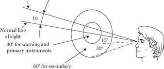
1. Visibility—The operator must be able to see all instruments from his normal workplace without abnormal movements of his head or body (see Figure 6.2). The following design principles for positioning with regard to the visibility of different instruments on a panel should be followed: a. Warning signals and primary instruments: Reading of this category of instrument must be possible without the operator having to change the position of the head or the eyes from the normal line or position.
|
Horizontal
instruments FIGURE 6.2 Positioning of visual instruments. |
b. Secondary instruments: Reading can be done by changing the direction of the eyes but not the position of the head.
c. Other (infrequently-used) instruments: These instruments do not need to lie within the normal line of vision.
2. Identification—The operator must be able to find an instrument or a group of instruments rapidly without making mistakes. The individual instruments or groups of instruments should be separated in order to facilitate identification. Other ways to differentiate instruments are:
a. Different colours[13] or shading between the main and subsidiary panels.
b. Lines of different colours around the instruments.
c. A subsidiary panel away from the main panel.
d. A subsidiary panel sunk into the main panel.
Apart from the above, textual signs can be used. Rules governing the use of such signs are:
a. Positioning must be consistent, e. g., either over or under the instrument.
b. All panels, groups of instruments, and individual instruments must have signs. The size of the signs (text) should increase by 25% from smallest to largest; for example, single instruments are smallest, then groups, and so on.
c. The text must be horizontal.
d. The signs that are not related to function, such as manufacturer’s name plates, must be positioned so that they cannot be confused with functional signs.
e. Signs should not be put on curved surfaces.
3. Stereotypical behaviour—Both control devices and instruments should be positioned and give the readings that people would expect. Human beings often have a predetermined expectation, which is based on experience, of what will happen in different situations. An example is that of a reverse gear, which should be in such a position that the gear lever has to be moved backward to engage it.
Particular changes on an instrument produce certain expectations,
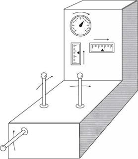
e. g., the clockwise movement of the pointer on a circular dial indicates an increase. Certain relationships between the movement of a pointer on an instrument and the movement of the controlling device are also expected (see Figure 6.3).
a. Learning times will be reduced.
b. If account has not been taken of the stereotypical expectations, there is a great risk that accidents will occur, together with poorer performance, in emergency situations.
During the computerisation of a process control system, there is often a tendency to remove the overall display panels (which give an overview and general description of the elements in the process, and which may also have indicators for various functions in the process). This is usually a mistake, as the display panels often fulfil
|
FIGURE 6.3 Expected relationships between instruments and levers; arrows represent the direction of increase. |
a more important function in the computerised system than in the traditional one. The traditional panel usually gives an overview of the status and build-up of the process. Visual display units (VDUs) give a considerably poorer overview, so they need to be supplemented with general overview information. Only a limited amount of information can be shown at any one time on a VDU, so the information is generally presented in sequence. Even if the operator has access to several screens (parallel presentation), he or she is often forced to leaf through different frames on the VDU in order to build up a picture of the status of the system. This may be troublesome in situations that demand rapid action, and in some cases may be dangerous. A functional overview display panel, which has various indicators on it, and maybe also instruments, can be an important supplement here.
Figure 6.3 shows recommendations on the natural relationships between functions in the process and the information devices, and between the information and control devices. It is difficult when using computerised systems to bring about these natural relationships. The information on the VDU screen does not usually bear any logical resemblance to what is happening in the process. The control movements on the keyboard are often even less related to what is happening in the process (for example, increase or reduction should be represented by movement of a lever forwards and backwards respectively). Even in computerised systems, one should strive to maintain these relationships.
The operator should have the VDU screen within close view; normally, a keyboard or some other computer-controlled device is at his or her disposal. These controls should be placed so that the operator can position them with his or her arm in a comfortable, relaxed position. Further recommendations on the positioning of the table, work surfaces, and control panels are given in relevant sections in this chapter.
Chapter 4 presents the development of display technologies that offer many opportunities for new ways of designing dynamic overview displays. The general principles presented below give some design guidelines which are also highly relevant for the new generation of display technology.


