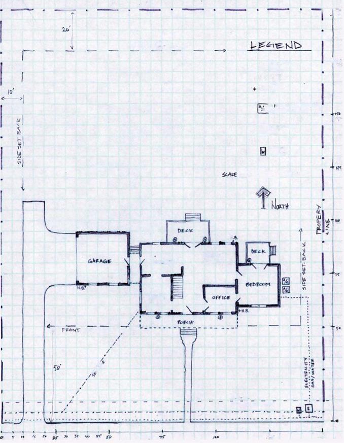
All good ideas begin with a plan. Homeowners who begin installation without a developed plan may end up unhappy with the results. An unplanned home landscape built in separate steps sometimes does not coordinate well together when completed. Form a detailed overall plan before beginning installation. A good landscape design can provide a plan for phased installation, allowing a large or expensive landscape to be completed in stages as resources become available. A plan is a logical series of decisions that becomes the best overall idea.
There are seven basic steps to creating a landscape plan:
1. Develop a base plan
2. Conduct a site analysis
3. Assess family needs and desires
4. Locate use areas
5. Design outdoor use areas
6. Select and place plant symbols on plan
7. Establish priorities for implementation
Step 1. Develop base plan or plot plan
Purpose
Begin by developing a simple, scaled drawing of your existing landscape from a bird’s-eye view. This map, or base plan, should accurately locate the property lines, house, drives, walks, fences, utility lines, existing trees, and other features that can affect your landscape development. There are many ways to measure and record the features of your landscape onto paper. Try one or more of the following techniques.
Identifying Your Property Lines
This step can be much easier if you obtain a map that shows the property lines and the house’s location on the property. This may be a plat, a deed map, the architect’s or builder’s plans, or a topographical plan with contour lines showing the site’s elevation or graduation. The map may include the fixed structures and hardscape—house, driveway, sidewalks, fences, walls, etc.
Depending on where you live, a plat may have been included in the papers you acquired when you purchased your home. If not, you may be able to obtain it from the city or county assessor’s office. While you’re there, you can request a copy of all local ordinances regarding easements, height restrictions, building codes, and any other regulations that could impact your landscaping project.
If you have difficulty verifying your property lines, you may need to call a registered land surveyor to locate and verify your property boundaries. You may use this survey plan as the basis for your scaled drawing.
Getting Started
Develop your base plan by using a piece of tracing paper to make a rough sketch of your property. If you have a large property, you may want to break the base plan into several drawings (front, side, or backyard areas of the landscape) or use large paper. Regardless, your sketch should show your property’s general shape. Be sure to label the street and property lines. A directional arrow to indicate north is useful.
Gathering Equipment
Gather the equipment needed to take and record accurate measurements: 50- or 100-foot tape measure, pencils, erasers, and a large clipboard to hold your tracing paper. You may find that a measuring wheel works better for you than a tape measure. You will also need graph paper or a drawing scale to transfer your rough sketch into a scaled drawing. It is better to have a partner to help you take measurements using a tape measure. If you don’t have help, use a long screwdriver to go through the loop on the end of the tape and into the ground to hold it in place as you measure.
Taking Measurements
Now take the rough sketch of your property and begin to take measurements using the techniques described in the following sections. After all the measurements have been made, the rough sketch can be brought back indoors and a final base plan drawn to scale. For properties smaller than an acre, a scale of 1 inch = 10 feet (measure with an engineer’s scale), or Vs" = 1 foot (measure with an architect’s scale) are appropriate drawing scales. For planting beds having a large variety of species, the architectural scale of W" = 1 foot may be chosen. This larger scale can be a good choice when needing to show greater detail, such as in beds located adjacent to buildings or hardscape areas. Construction drawings for a building (also called floor plans) are frequently drawn in W" scale, and these can be used as a base map for your planting plan. Use an architectural ruler or an engineer’s scale to measure. These supplies are available at most drafting or art shops. See Figure 3 for a sample base plan.
The base plan should show the following information:
• All property lines
• Bodies of water (streams, lakes, ponds, low areas)
• Buildings, including
– floor plan with doors and windows
– downspouts
– outside water spigots
– outside electrical outlets
– decks and overhangs
– air conditioner units
– utility connections and meters
– driplines
• All walls, fences, utility boxes and poles, fire hydrants, etc.
• Roads, drives, parking areas, walks and paths, patios, swimming pools
• On – and off-site utilities, above – and belowground, including electric, telephone, gas, water, sewer, septic tanks, and field drains. Notify Miss Utility (#811) to have underground utilities located.
• Existing vegetation, especially large trees
• Off-site elements including adjoining roads and drives, bodies of water, and structures
• Compass directions showing north, east, south, and west
• The scale size of the base plan Identifying Property Lines
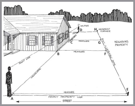
Find your property lines by using the plat, survey records, or other records. Measure each property line with a tape measure and record it on your rough sketch. If your property has side boundaries that are not parallel or if your home is not parallel to at least one boundary, you must make an additional
|
|
|
|
|
|
|
|
|
|
|
|
|
|
|
|
|
|
|
|
|
|
|
|
|
|
|
|
|

 measurement to draw the correct corner angles in your final drawing. Ask another person to help you by standing on the property line while you sight along the house wall toward them. Ask them to move to the left or to the right, as needed, to be in line with your sight line down the wall. Then measure the distance from your helper along the boundary line to the nearest corner. (Reference points D to H in Figure 4.)
In a similar manner, ask your helper to stand on the front property line. Align him or her on your sight line as you look down the side wall of the house toward him/her. Again, record the distance from your helper to each property line. (Reference points A to E and A to D in Figure 4.)
Locating House on Property
Accurately locate the front corner of the house by first measuring Fi9ure 4 Measuring property lines. the distance from the street to the corner of the house (A to B as shown in Figure 4). Then measure the distance from the side property line to the front corner (B to F as shown in Figure 4). Locate a back corner of the house by measuring from the street to the back corner (A to C), and then measure from the back corner to the side property line (C to G).
You can record the measurements of each side of the house by using a set of blueprints of your home, by using the survey record, or by making measurements of each side. Be sure to indicate location of doors, width of windows, and height above ground level. Don’t forget to measure heights from ground level of porches and decks. See Figure 5 for the method of measuring windows and doors.
Locating Outlying Landscape Features
You are now ready to locate the other features of the property. These features include above – and belowground utilities such as gas, water, electric, telephone, and sewer lines. Also included are TV cable, septic tank, field lines, utility meters, water faucets, roof overhangs, retaining walls, and fences.
Don’t forget to include existing trees and other plants you want to keep in the new landscape design. Depending on the quantity and locations of existing plants you plan to remove, you may also want to include them, especially if you will not be performing the removal yourself. If all of these features will not fit easily onto one base plan, you can create other plans to include features such as existing plant material and physical structures. See Figure 6.
|
Figure 6. Inventory of existing plant material and physical structures. Drawing by Richard Martin III. |
|
4′ MMttN |
Natural features such as ditches, ravines, and steep slopes should be included. Also include neighboring buildings and existing vegetation, especially large trees, that will impact your landscape. You can locate these outlying features on your rough sketch by measuring in two directions from a known reference point, such as the house, street, or property line.
See Figure 7 for a method of using the sight line of the house to locate an existing tree in the landscape. Trees or other feature points can also be located by a triangulation measurement (Figure 8). Measure the distance from two known points (A and B), marking on the base plan where these two distances meet along radii drawn by a compass.
1. Record the measurement from the house corner straight out to point A, which is aligned with the corner of the first tree.
2. Measure from point A to the center of the first tree, point B.
3. Measure straight out from point B to the point that aligns with the center of the second tree, point C.
4. Measure straight out from point C to the center of the second tree, point D.
Figure 7. Measuring to outlying objects.


