1.3 Testing procedure
In order to verify the effectiveness of analytical and numerical analyses some experimental measurements, for the damaged and repaired panels, are carried out. The tests are performed at room temperature in a 100 kN Metrocom Engineering SpA servo-hydraulic test machine. The tests are focused to evaluate the fatigue life of the structures under cycling loads at R=0 as described in Section 2 – Table 4. Each test is performed up to the complete fracture of the panel. In each test the number of the cycles, the crack growth and the SIF are evaluated. In particular the SIF is measured at the crack tip using three measurement grids strain-gauges. A National Instrument data acquisition system is used to acquire the load and strain measurements during the tests.
In all the experimental tests the panel surface is treated with a solvent to clean and remove any impurities and / or contamination from the surface and subjected to a local mechanical abrasion to increase and activate the contact surfaces between the metal panel and the composite patch. In the configuration A4 reported in the Table 8, the surface is subjected to a treatment of pickling sulfur chromium for aluminum alloys according to UNI EN 2334:1998 – Aerospace Division.
|
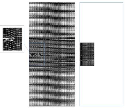
Fig. 4. Finite element model of the plate repaired with the composite patch 5.2 Experimental results Among all the possible combinations of patch and adhesive types and loading conditions, a subset of tests is carried out. The experimental configurations, discussed in the present work, are summarized in Table 8: |
|
Configuration Name |
Patch Type |
Adhesive Type |
Loading Condition |
Surface Treatment |
|
A1 |
Type 1 |
EA956 |
Test 2 |
Yes |
|
A2 |
Type 2 |
FM 73 |
Test 2 |
Yes |
|
A3 |
Type 2 |
AF163-2K |
Test 2 |
Yes |
|
A4 |
Type 2 |
AF163-2K |
Test 2 |
Yes |
|
B1 |
Type 1 |
EA956 |
Test 3 |
Yes |
|
B2 |
Type 1 |
EA956 |
Test 3 |
Yes |
|
Table 8. Experimental configurations |
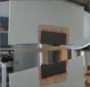
A good repeatability is found for the configurations A1+A4 as the load amplitude is a moderate percentage of the ultimate static load. The configurations B1 e B2 are characterized by an higher load amplitudes. Moreover for the configuration B1 the patch is bonded using the technique of mechanical compression; on the contrary for the configuration B2 it is bonded using the vacuum bag technique. Therefore the results of the configurations B1 and B2 are presented separately in order to show the scatter of the experimental results, summarized in the Tables 9 and 10. The configurations A1 showed the best performances in terms of stress level and fatigue life. The configuration A1 is repaired with a patch "Type 1" that is thicker and therefore introduces a higher stiffness by increasing the fatigue life, but amplifies the bending in the panel. The configurations A2+A4, with the same type of bonded patch, show the role of both the adhesive layer and the surface treatment. In particular the configuration A4 provides a fatigue life comparable with configuration A1 although the measured SIF for A4 is the highest among the configurations A. In Fig. 5 it is shown how for the configuration A4 the crack propagates through the composite patch leading to the simultaneous fracture of the metal panel and of the patch.
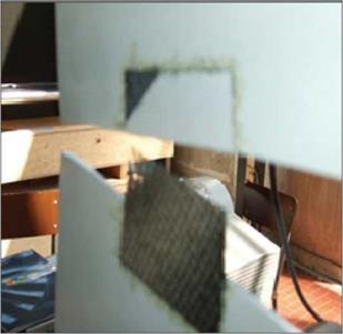
In other configurations the crack propagates in the adhesive layer and the patch slid over the panel surface as showed in Fig. 6.
|
Configuration Name |
Experimental |
Numerical |
Difference [%] |
|
A1 |
13.61 |
12.92 |
5.1 |
|
A2 |
14.85 |
15.59 |
-5.0 |
|
A3 |
15.11 |
15.75 |
-4.3 |
|
A4 |
16.83 |
15.75 |
6.4 |
|
B1 |
17.89 |
17.36 |
3.0 |
|
B2 |
18.02 |
17.36 |
3.7 |
|
Table 9. SIF – Ki [MPaVm]: Experimental and numerical results |
|
Configuration Name |
Experimental |
Numerical |
Difference [%] |
|
A1 |
21770 |
23188 |
-6.51 |
|
A2 |
18843 |
21207 |
-12.50 |
|
A3 |
19375 |
21268 |
-9.77 |
|
A4 |
21450 |
21268 |
0.85 |
|
B1 |
4425 |
5235 |
-18.30 |
|
B2 |
4926 |
5235 |
-6.27 |
|
|
|
|
|
5.3 Comparison of numerical and experimental results
The developed finite element models are not able to take account of the difference between the configurations A3, A4 and B1, B2. Therefore the same numerical value is reported in the Tables 9 and 10. The comparison of the SIF shows a good agreement between experimental and numerical results. On the contrary, the numerical results, in general, overestimated the experimental fatigue life. The small differences in terms of SIF values lead to a larger overestimation of the fatigue life. The curing procedure of the patch on the metallic panel introduces random factors that cannot be easily accounted for in the finite element model reducing its predictive capabilities.


